8-52 Phaser 7750 Printer Service Manual
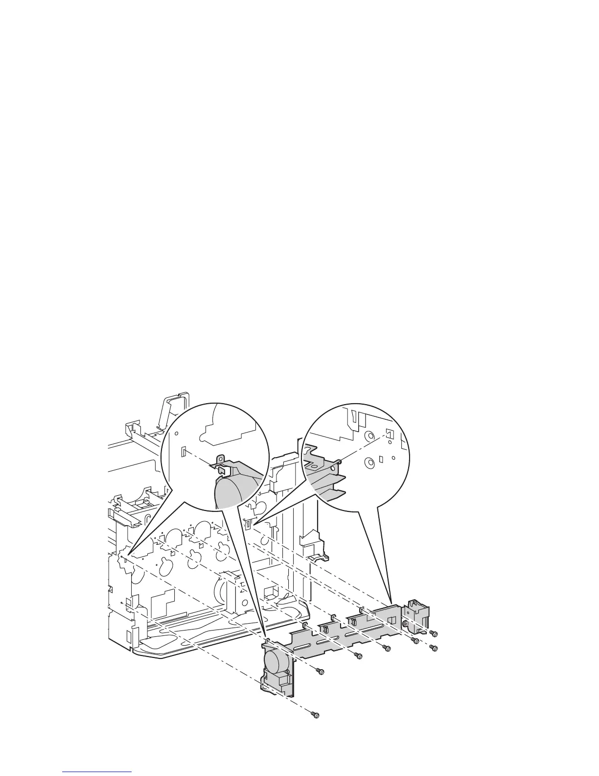
Imaging Unit Drive Assembly
1. Remove the rear cover, see page 8-6.
2. Remove the right side cover, see page 8-4.
3. Remove the 3.3 VDC and 5 VDC Low-voltage power supply, see page 8-44.
4. Remove the 24 VDC Low-voltage power supply, see page 8-46.
5. Remove the T2 High-Voltage power supply, see page 8-47.
6. Remove the engine control interface board and bracket, see page 8-43.
7. Disconnect the wiring harnesses (1 to YMC and 1 to K) to the Print Engine Drive
Assembly.
8. Remove the 2 screws securing the finisher connector (now accessible after
removing the right cover assembly) and let it hang loose.
9. Remove 1 screw that is accessible through the frame access hole near the finisher
connector.
10. Remove the remaining 7 screws that secure the imaging unit drive assembly to
the printer frame.
11. Lift the imaging unit drive assembly up and out of the printer.
Note
Some wires will have to be removed from their clamps to clear the drive
assembly.
7750-122

 Loading...


