General Troubleshooting 4-19
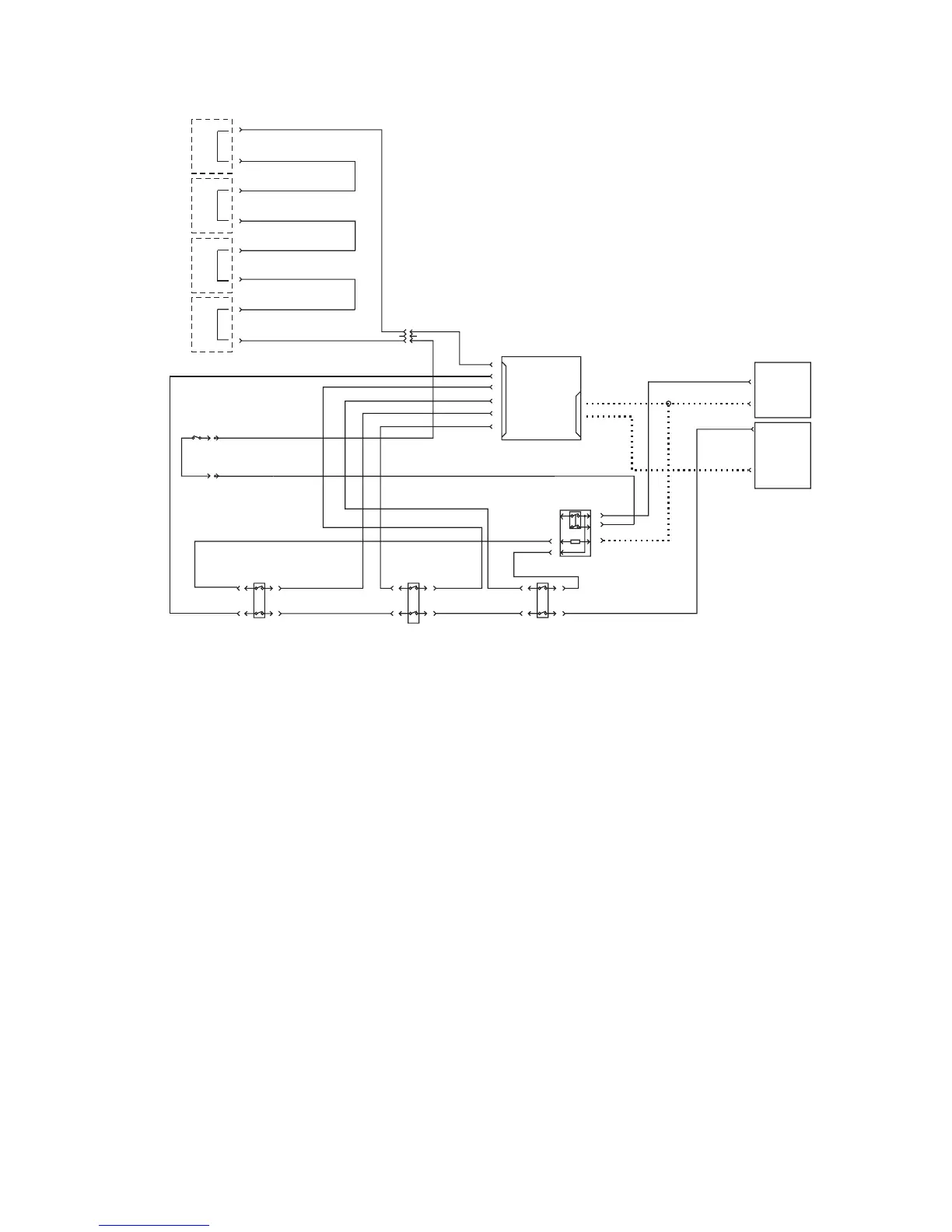
Interlock Circuit Diagram
The +24 VDC Interlock Circuit
The 24 VDC interlock circuit runs from the 24 VDC LVPS to the L/H door interlock
switch, the R/H door interlock switch, and the front door interlock switch back to the
engine control interface board, then into the engine control board. Opening this circuit
prevents the laser unit and the high-voltage power supplies from operating.
1. Check to see if the front door is getting +5 VDC.
2. With all doors closed and printer power on, check for +24 VDC between P531-1
of the engine control board and frame ground.
3. If +24 VDC is not present, see See “Troubleshooting the 24 VDC LVPS” on
page 13. to verify the 24 VDC LVPS is working.
4. If +24 VDC is present, then check the LH cover interlock switch, the RH cover
interlock switch and the front cover interlock switch.
PRINT CARTRIDGE CRUM CONNECTORS
WASTE CARTRIDGE
INTLK SW
FRONT COVER INTLK SW R/H COVER INTLK SW LH COVER INTLK SW
LVPS
LVPS
INTERFACE
BOARD
C
K
M
Y
GRY
GRY
GRY
GRY
GRY
GRY
GRY
GRY
ORN
ORN
ORN
ORN
GRY
GRY
GRY
VIO
VIO
GRY
LD
POWER
RELAY
24V
5V
P536
P537
J631
1
1
2
3
3
4
5
5
6
6
7
S7700-432

 Loading...


