4-79
HANDLEBAR
4. Install:
• Front brake master cylinder assembly
Refer to “INSTALLING THE FRONT BRAKE
MASTER CYLINDER” on page 4-47.
5. Install:
• Handlebar switch holder
• Handlebar switch (left)
Align the projection “a” on the handlebar switch
(left) with the hole “b” in the handlebar.
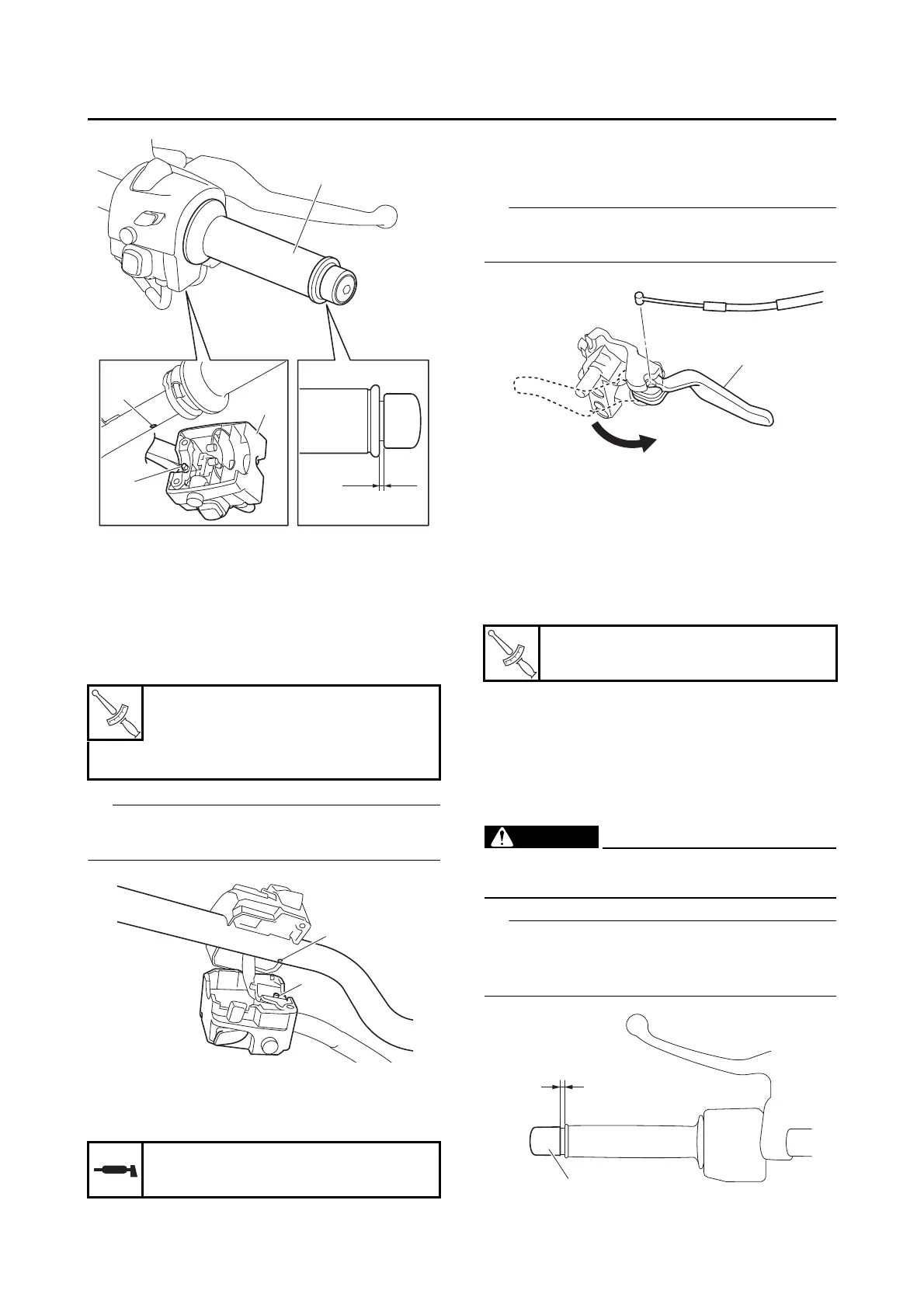
6. Lubricate:
• Rear brake lock cable
(to cable end)
7. Connect:
• Rear brake lock cable
(to rear brake lock lever)
Rotate the lever to the position “a”, and then in-
stall the rear brake lock cable.
8. Install:
• Rear brake master cylinder assembly
Refer to “INSTALLING THE REAR BRAKE
MASTER CYLINDER” on page 4-62.
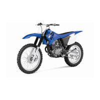
9. Install:
• Handlebar grip
• Grip end “1”
a. Apply a thin coat of rubber adhesive onto
the end of the left handlebar.
b. Slide the handlebar grip over the end of the
left handlebar.
c. Wipe off any excess rubber adhesive with a
clean rag.
EWA13700
Do not touch the handlebar grip until the rub-
ber adhesive has fully dried.
There should be 1–3 mm (0.04–0.12 in) of clear-
ance “a” between the handlebar grip and the grip
end.
Handlebar switch holder screw
3.5 N·m (0.35 kgf·m, 2.6 lb·ft)
Handlebar switch screw (left)
1.8 N·m (0.18 kgf·m, 1.3 lb·ft)
Recommended lubricant
YAMAHA GREASE “F”
Grip end
26 N·m (2.6 kgf·m, 19 lb·ft)