3-10
PERIODIC MAINTENANCE
Adjusting the throttle body synchronization
1. Adjust:
• Throttle body synchronization
a. Start the engine, warm it up for several min-
utes, and then let it run at the specified en-
gine idling speed.
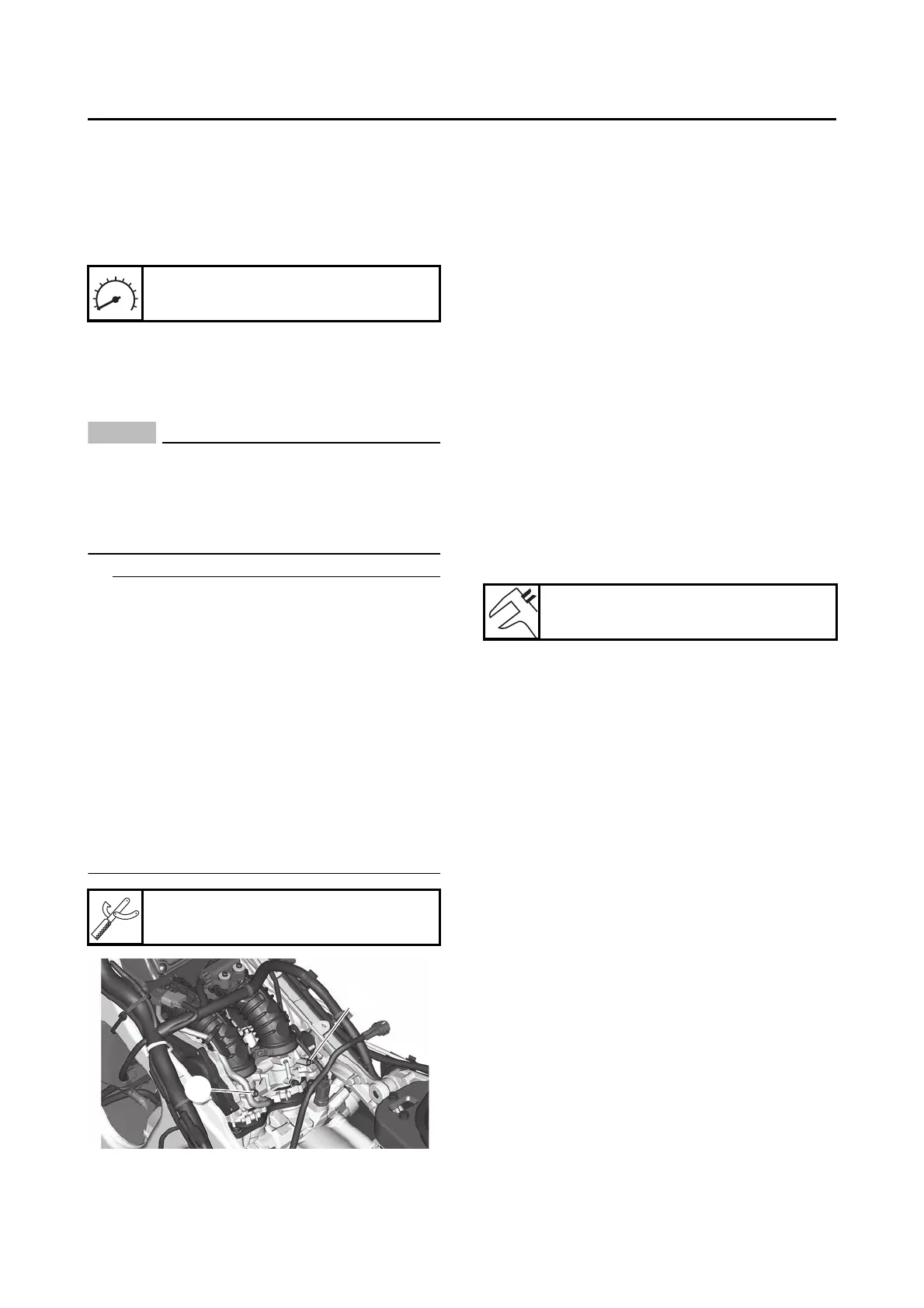
b. Using the throttle body that has the bypass
air screw “1” with a white paint mark as the
standard, adjust the other throttle bodies by
turning its bypass air screw “2” in or out.
ECA21300
Do not turn the bypass air screw (white paint
mark) of the throttle body that is the stan-
dard. Otherwise, the engine may run roughly
at idle and the throttle bodies may not oper-
ate properly.
• Turn the bypass air screw using the carburetor
angle driver.
• After each step, rev the engine two or three
times, each time for less than a second, and
check the synchronization again.
• If a bypass air screw was removed, turn the
screw in fully and be sure to synchronize the
throttle bodies.
• If the throttle body synchronization can not be
adjusted using the bypass air screw, clean or
replace the throttle bodies.
• The difference in vacuum pressure between
the throttle bodies should not exceed 1.33 kPa
(10 mmHg).
2. Stop the engine and remove the measuring
equipment.
3. Install:
• Intake air pressure sensor hose
•Cap
4. Install:
• Fuel tank
Refer to “FUEL TANK” on page 7-1.
• Footboard
• Rear side cowling assembly
• Side cover
• Fuel tank cover assembly
• Center cover
Refer to “GENERAL CHASSIS (2)” on
page 4-11.
• Bottom center cowling
• Side panel
• Bottom side cowling
Refer to “GENERAL CHASSIS (1)” on
page 4-1.
5. Adjust:
• Throttle grip free play
Refer to “CHECKING THE THROTTLE
GRIP” on page 3-33.
EAS31318
CHECKING THE THROTTLE BODY JOINTS
1. Remove:
• Bottom side cowling
• Side panel
• Bottom center cowling
Refer to“GENERAL CHASSIS (1)” on
page 4-1.
• Center cover
• Fuel tank cover assembly
• Side cover
• Rear side cowling assembly
• Footboard
Refer to “GENERAL CHASSIS (2)” on
page 4-11.
• Fuel tank
Refer to “FUEL TANK” on page 7-1.
2. Check:
• Throttle body joint
Cracks/damage Replace.
3. Install:
• Fuel tank
Refer to “FUEL TANK” on page 7-1.
• Footboard
• Rear side cowling assembly
• Side cover
• Fuel tank cover assembly
Engine idling speed
1100–1300 r/min
Carburetor angle driver 2
90890-03173
Throttle grip free play
1.0–3.0 mm (0.04–0.12 in)