5-33
CYLINDER AND PISTONS
EAS30293
CHECKING THE PISTON PINS
The following procedure applies to both of the
piston pins.
1. Check:
• Piston pin
Blue discoloration/grooves Replace the
piston pin and then check the lubrication sys-
tem.
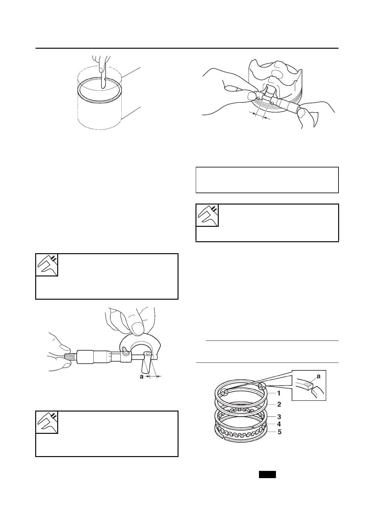
2. Measure:
• Piston pin outside diameter “a”
Out of specification Replace the piston pin.
3. Measure:
• Piston pin bore inside diameter “b”
Out of specification Replace the piston.
4. Calculate:
• Piston-pin-to-piston-pin-bore clearance
Out of specification Replace the piston pin
and piston as a set.
EAS30294
INSTALLING THE PISTON AND CYLINDER
The following procedure applies to all of the pis-
tons and cylinders.
1. Install:
• Oil ring expander “1”
• Lower oil ring rail “2”
• Upper oil ring rail “3”
• 2nd ring “4”
• Top ring “5”
(into the piston)
Be sure to install the top and 2nd rings so that
the manufacturer marks or numbers “a” face up.
2. Install:
• Piston “1”
• Piston pin “2”
• Piston pin clip “3”
a. Bottom of cylinder
b. Upper of cylinder
Piston pin outside diameter
16.995–17.000 mm
(0.6691–0.6693 in)
Limit
16.975 mm (0.6683 in)
Piston pin bore inside diameter
17.002–17.013 mm
(0.6694–0.6698 in)
Limit
17.043 mm (0.6710 in)
Piston-pin-to-piston-pin-bore clearance =
Piston pin bore inside diameter -
Piston pin outside diameter
Piston-pin-to-piston-pin-bore
clearance
0.002–0.018 mm (0.0001–0.0007
in)