5-20
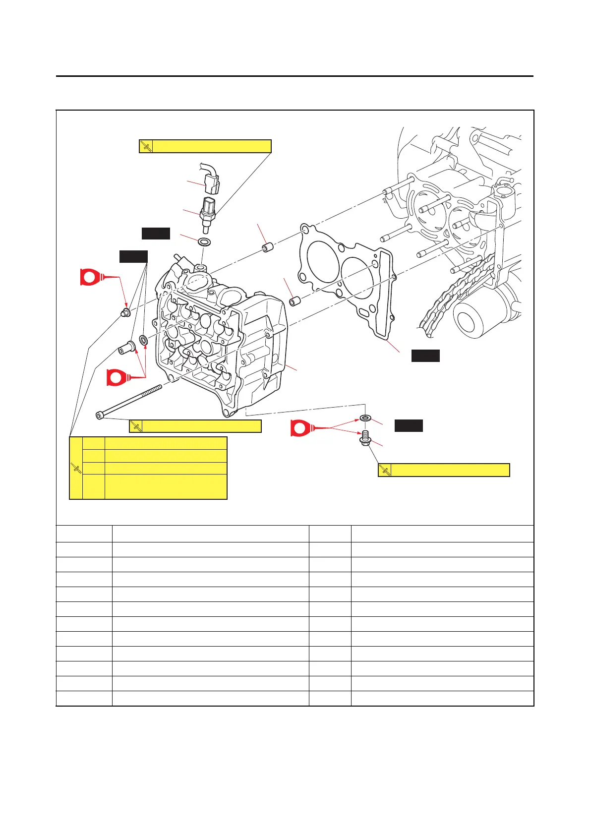
CYLINDER HEAD
EAS20044
CYLINDER HEAD
Removing the cylinder head
*
Following the tightening order, loosen the bolt one by one, and then retighten it to the specified torque and the
specified angle.
Order Job/Parts to remove Q’ty Remarks
Engine Refer to “ENGINE REMOVAL” on page 5-7.
Camshafts Refer to “CAMSHAFTS” on page 5-12.
Thermostat Refer to “THERMOSTAT” on page 6-9.
1 Coolant temperature sensor coupler 1 Disconnect.
2 Coolant temperature sensor 1
3Gasket 1
4 Cylinder head 1
5 Cylinder head gasket 1
6 Dowel pin 2
7 Engine oil check bolt 1
8Gasket 1
New
New
E
E
1st
3rd
*4th
2nd
10 N·m (1.0 kgf·m, 7.4 lb·ft)
20 N·m (2.0 kgf·m, 15 lb·ft)
28 N·m (2.8 kgf·m, 21 lb·ft)
6 N·m (0.6 kgf·m, 4.4 lb·ft)
Specified angle 180˚
10 N·m (1.0 kgf·m, 7.4 lb·ft)
15 N·m (1.5 kgf·m, 11 lb·ft)
15 N·m (1.5 kgf·m, 11 lb·ft)
4
(2)
(2)
(4)
6
6
3
New
5
New
8
7
2
1
E