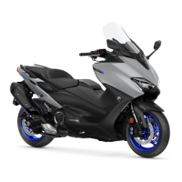
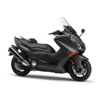
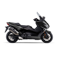
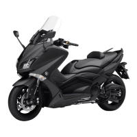
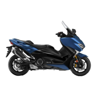
Do you have a question about the Yamaha TMAX TECH MAX 2020 and is the answer not in the manual?
Provides dimensions, weight, loading capacity, and model details for XP560E, XP560D_RUS, XP560D_ZAF.
Details combustion cycle, cooling system, valve train, displacement, bore, stroke, compression, fuel, and engine oil.
Covers frame, wheels, tires, front and rear brakes, and front/rear suspension specifications.
Lists system voltage, ignition system, engine control unit, ignition coil, spark plug cap, and charging system details.
Specifies torque values for engine and chassis items, including nuts, bolts, and unions.
Procedure for using the YDT to check the vehicle, including removing covers, connecting to the coupler, and checking DTCs.
Procedure for adjusting valve clearance on a cold engine, including removing parts and calculating valve pad thickness.
Details on measuring compression pressure, including procedure and specifications.
Step-by-step instructions for removing the exhaust assembly and the engine.
Procedures for removing, checking, and installing camshafts, including lobe dimensions and runout.
Instructions for removing, checking, and installing the cylinder head, including warpage measurement.
Procedures for removing, checking, and installing valves, valve springs, and related components.
Instructions for removing, checking, and installing cylinders and pistons, including ring and pin measurements.
Procedure for removing the clutch assembly, including draining engine oil and coolant.
Detailed steps for disassembling the clutch, including removing clips, stopper plates, springs, and plates.
Instructions for removing engine, cylinder head, pistons, starter motor, generator, and clutch assemblies.
Procedure to remove the crankshaft assembly, balancer cylinder, and oil seal.
Steps for removing connecting rod caps, connecting rods, and big end bearings.
Procedure to measure crankshaft runout and check journal, pin, and bearing surfaces.
Procedure to remove secondary shaft, collars, O-rings, gears, drive axle, and wheel gears.
Information about the Yamaha Diagnostic Tool (YDT) and its usage for identifying malfunctions.
Detailed circuit diagram for the Engine Control Unit (ECU).
General troubleshooting steps for fuel injection system issues, focusing on MIL and DTC checks.
Table detailing DTCs related to the fuel injection system, including probable causes and symptoms.
Table listing DTCs related to the ABS system, their symptoms, and check points.
Wiring diagram for the ABS system.
Troubleshooting steps for when only the ABS warning light fails to illuminate.
Troubleshooting steps when all indicator lights fail to illuminate.
Troubleshooting steps when the ABS warning light remains on.
Troubleshooting steps when only the ABS ECU fails to communicate.
Troubleshooting steps when both ABS ECU and FI ECU fail to communicate.
Table listing DTCs, their symptoms, probable causes, vehicle symptoms, and fail-safe operations.
| Displacement | 562 cc |
|---|---|
| Compression Ratio | 10.9:1 |
| Lubrication System | Wet sump |
| Fuel System | Fuel Injection |
| Ignition System | TCI |
| Starter System | Electric |
| Transmission System | V-Belt Automatic |
| Final Drive | Belt |
| Front Suspension System | Telescopic fork |
| Front Travel | 120 mm |
| Rear Suspension System | Swingarm |
| Rear Travel | 117 mm |
| Front Tyre | 120/70-15 |
| Seat Height | 800 mm |
| Wheel Base | 1, 575 mm |
| Minimum Ground Clearance | 135 mm |
| Wet Weight | 220 kg |
| Engine Type | Liquid-cooled, 4-stroke, DOHC, 4-valve |
| Maximum Torque | 55.7 Nm (5.7 kg-m) @ 5, 250 rpm |
| Front Brake | Dual 267 mm discs |
| Rear Brake | Single hydraulic disc |
| Rear Tyre | 160/60-15 |
| Fuel Tank Capacity | 15 litres |
| Features | Heated Grips, Adjustable windscreen, Traction control |

