4-99
REAR SHOCK ABSORBER ASSEMBLY
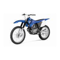
• When installing the oil seals “2” to the relay
arm, face the character stamp of the oil seals
outside.
• Press in the oil seal so it does not protrude
from the end surface of the relay arm.
• Install the connecting arm so that the stamp
mark “B67” is facing outward. The stamp mark
can be facing either up or down.
• Install the rear shock absorber assembly upper
bolt and connecting arm bolt from the left.
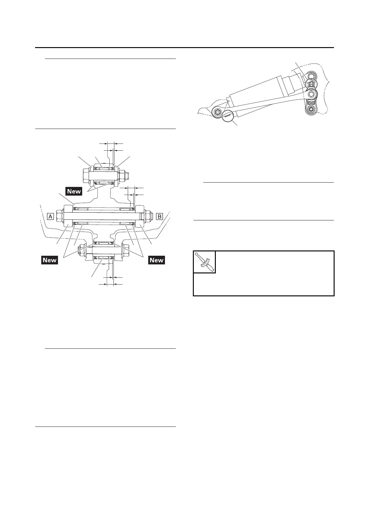
• Install the relay arm so that stamped mark “a”
is positioned as shown in the illustration.
• Install the rear shock absorber assembly so
that the label is facing downward.
• Install the rear shock absorber assembly so
that the rebound damping adjusting screw “b”
is facing downward. (for XP560D)
EAS30225
INSTALLING THE REAR SHOCK
ABSORBER ASSEMBLY
1. Install:
• Rear shock absorber assembly
• Install the rear shock absorber assembly lower
bolt and relay arm bolt from the right.
• Install the rear shock absorber assembly with
the swingarm down.
2. Tighten:
• Rear shock absorber assembly lower nut
• Relay arm nut
3. Relay arm
4. Connecting arm
5. Rear shock absorber assembly
A. Left side
B. Right side
Rear shock absorber assembly
lower nut
75 N·m (7.5 kgf·m, 55 lb·ft)
Relay arm nut
50 N·m (5.0 kgf·m, 37 lb·ft)