5-80
CRANKSHAFT
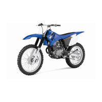
• Align the projections “a” on the big end bear-
ings with the notches “b” in the connecting rods
and connecting rod caps.
• Be sure to reinstall each big end bearing in its
original place.
• Make sure the “Y” marks “c” on the connecting
rods face towards the left side of the crank-
shaft.
• Make sure the characters “d” on both the con-
necting rod and connecting rod cap are
aligned.
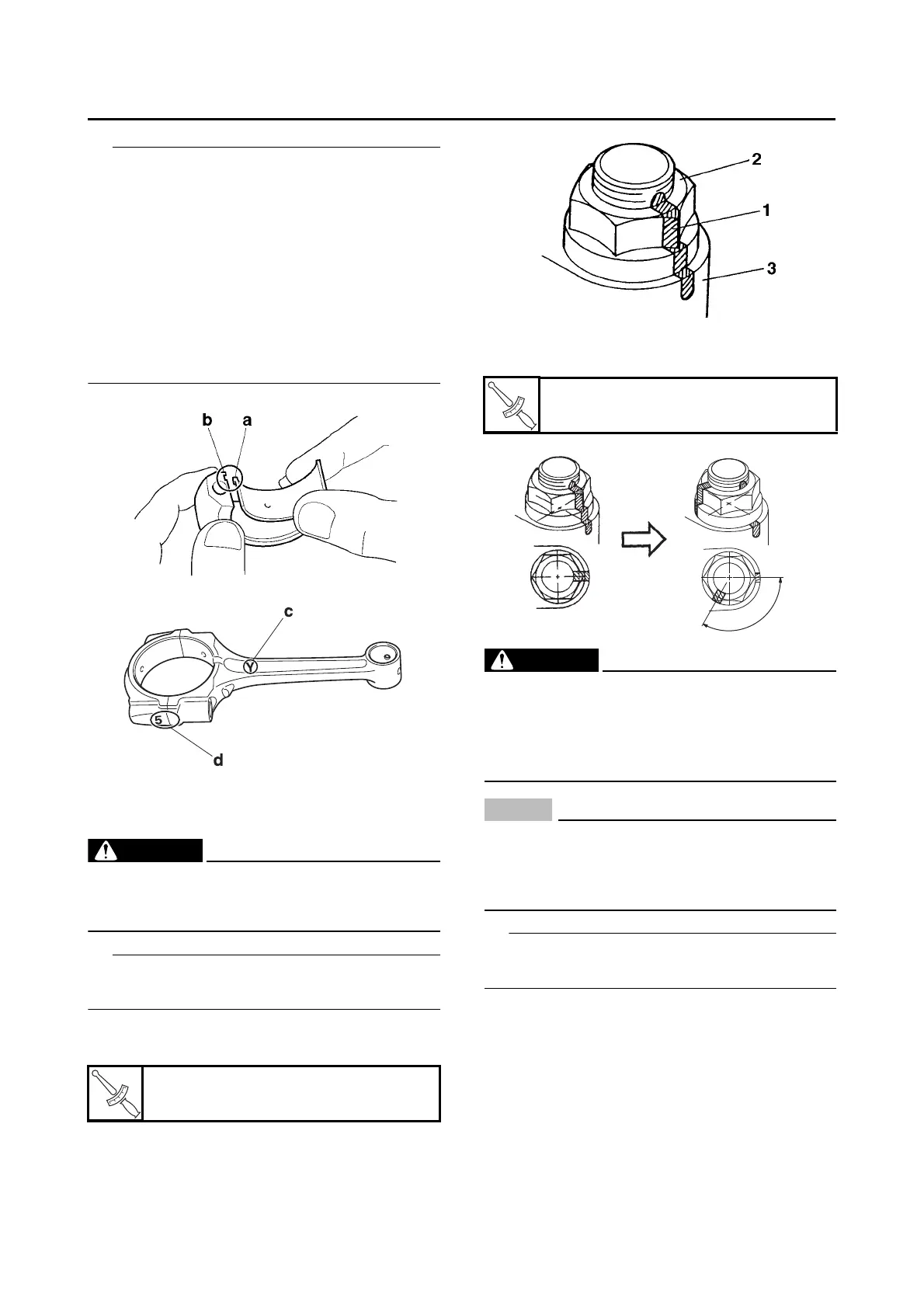
4. Tighten:
• Connecting rod nut
EWA13390
• Replace the connecting rod bolts and nuts
with new ones.
• Clean the connecting rod bolts and nuts.
Tighten the connecting rod nuts using the follow-
ing procedure.
a. Tighten the connecting rod nuts with a
torque wrench.
b. Put a mark “1” on the corner of the connect-
ing rod nut “2” and the connecting rod cap
“3”.
c. Tighten the connecting rod nuts further to
reach the specified angle 120.
WARNING
EWA13400
If the connecting rod nut is tightened more
than the specified angle, do not loosen the
nut and then retighten it. Instead, replace the
connecting rod bolt and nut with a new one
and perform the procedure again.
NOTICE
ECA19930
• Do not use a torque wrench to tighten the
connecting rod nut to the specified angle.
• Tighten the nut until it is at the specified an-
gle.
On a hexagonal nut, note that the angle from
one corner to another is 60.
5. Install:
• Balancer big end bearing
• Balancer connecting rod
• Balancer connecting rod cap
(onto the crankshaft pin)
Connecting rod nut (1st)
16 N·m (1.6 kgf·m, 12 lb·ft)
Connecting rod nut (2nd)
Specified angle 120
 Loading...