Setting 4: Pulse Train Input
If b1-01 is set to 4 the frequency
reference must be provided by a pulse train signal at terminal RP that complies with the
following specification.
Pulse Train Input Specifications
Response Frequency 0.5 to 32 kHz
Duty Cycle 30 to 70%
High Level Voltage 3.5 to 13.2 V
Low Level Voltage 0.0 to 0.8 V
Input Impedance 3 kΩ
Verifying Pulse Train is Working Properly
• Make sure that b1-04 is set to 4 and H6-01 is set to 0.
• Set the pulse input scaling H6-02 to the pulse train frequency value that equals 100% frequency reference.
• Enter a pulse train signal
to terminal RP and check if the correct frequency reference is displayed. Try also with different
pulse train input frequencies.
n
b1-02: Run Command Selection 1
Parameter b1-02 determines the Run and Stop command source 1 in the REMOTE mode.
WARNING! Sudden Movement Hazard. Clear personnel, secure equipment, and check sequence and safety circuitry before starting
the drive. Failure to comply could result in death or serious injury from moving equipment.
No. Parameter Name Setting Range Default
b1-02 Run Command Selection 1 0 to 3 1
Setting 0: Digital Operator
Using this setting, the RUN and STOP keys
on the operator keypad will start and stop the motor. The LED in the LO/RE
key will be on to indicate that the Run command is assigned to the operator. The example below shows how the drive can
be operated if b1-02 is set to 0.
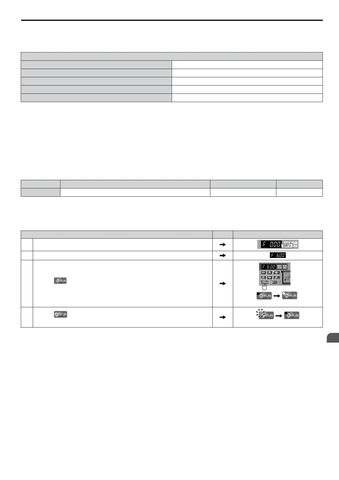
Step Display/Result
1. Turn on the power to the drive. The initial display appears.
2. Set the frequency reference to F6.00 (6 Hz).
3.
Press the
key to start the motor. The RUN indicator LED will light and the motor
will begin rotating at 6 Hz.
off on
4.
Press the key to stop the motor. The RUN light will flash until the motor comes
to a complete stop.
flashing
off
Setting 1: Control Circuit Terminal
This setting requires that the Run and Stop
commands are entered from the digital input terminals. The following sequences
can be used:
• 2-Wire sequence 1:
Two inputs (FWD/Stop-REV/Stop). Initializing the drive by setting A1-01 = 2220, presets the terminals S1 and S2 to
these functions. This is the default setting of the drive. Refer to Setting 40/41: Forward Run/Reverse Run Command
for 2-Wire Sequence on page 183.
• 2-Wire sequence 2:
Two inputs (Start/Stop-FWD/REV). Refer to Setting 42/43: Run and Direction Command for 2-Wire Sequence 2 on
page 183.
• 3-Wire sequence:
Inputs S1, S2, S5 (Start-Stop-FWD/REV). Initialize the drive by setting A1-01 = 3330 presets the terminals S1, S2 and
S5 to these functions. Refer to Setting 0: 3-Wire Sequence on page 177.
5.2 b: Application
YASKAWA ELECTRIC SIEP C710606 16C YASKAWA AC Drive – V1000 Technical Manual
119
5
Parameter Details

 Loading...


