Setting 31: PID Integral Hold
By configuring a digital input for Integral Hold (H1-0o = 31), the value of the integral component of the PID control is
locked as long as the input is active. The PID controller resumes integral operation from the hold value as soon as the
integral hold input is released. Refer to PID Block Diagram on page 133 for details.
Setting 32: Multi-Step Speed 4
Used to select the Multi-Step Speeds d1-09 to d1-16 in combination with the Multi-Step Speed inputs 1, 2 and 3. Refer
to d1-01 to d1-17: Frequency Reference 1 to 16 and Jog Reference on page 154 for details.
Setting 34: PID SFS Cancel
A digital input configured as a PID SFS Cancel input (H1-0o = 34) can be used to enable or disable the PID soft starter
and thereby canceling the Accel/Decel time b5-17. Refer to PID Block Diagram on page 133 for details.
Function 35: PID Input Level Selection
An input programmed
for this function can be used to switch the sign of the PID input. Refer to PID Block Diagram on
page 133 for more information on this function.
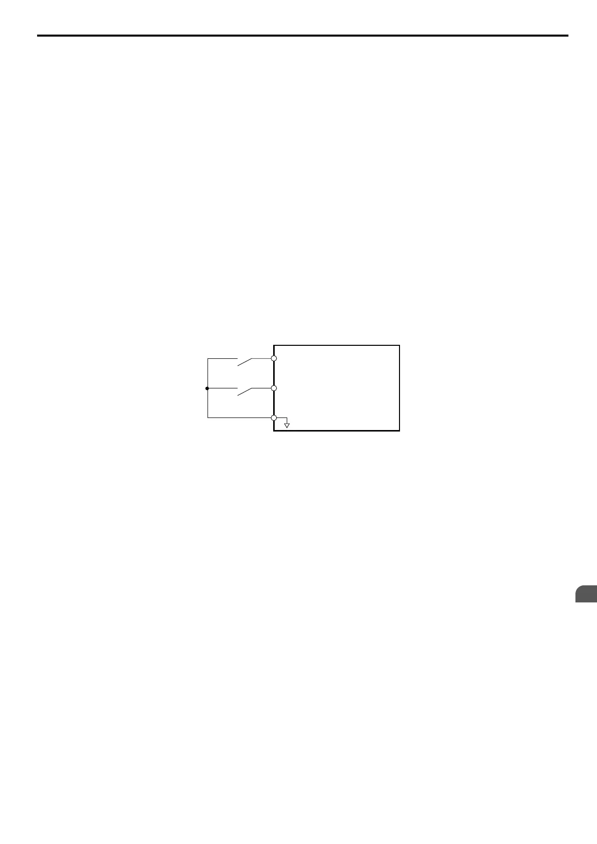
Setting 40/41: Forward Run/Reverse Run Command for 2-Wire Sequence
Sets the drive for 2-Wire sequence.
When the input set to 40 is closed, the drive operates in the forward direction. When the input set for 41 is closed, the drive
will operate in reverse. Closing both inputs at the same time will result in an external fault.
Note: 1. This function can not be used simultaneously with settings 42 and 43.
2. These functions are assigned to the terminals S1 and S2 when the drive is initialized for 2-Wire sequence.
3. Software versions 1013 and later require that the Forward run and Reverse run commands be set simultaneously.
S1
S2
SC
Drive
Forward Run
Reverse Run
Digital Input Common
Figure 5.53 Example Wiring Diagram for 2-Wire Sequence
Setting 42/43: Run and Direction Command for 2-Wire Sequence 2
Sets the drive for 2-Wire sequence 2.
When the input programmed for 42 is closed, the drive will operate in the selected direction. When the input opens, the
drive will stop. The input programmed for 43
selects the direction. If it is open, forward direction is selected; if it is closed,
reverse direction is selected.
Note: This function can not be used simultaneously with settings 40 and 41.
Setting 44/45/46: Offset Frequency 1/2/3 Addition
These inputs can be used to add offset frequencies d7-01, d7-02, and d7-03 to the frequency reference. Refer to d7-01 to
d7-03: Offset Frequency 1 to 3 on page 161 for details.
Setting 47: Node Setup
If the SI-S3/V option unit is connected, closing this terminal sets a node address for operation on a CANopen network.
Setting 60: DC Injection Braking
When a DC Injection Braking command is input while the drive is stopped, DC Injection Braking operation is activated.
When a Run command or a Jog command is input, DC Injection Braking is released. Refer to b2: DC Injection
Braking on page 123 for details on setting up the DC braking function.
The diagram below illustrates the DC Injection Braking function.
5.7 H: Terminal Functions
YASKAWA ELECTRIC SIEP C710606 16C YASKAWA AC Drive – V1000 Technical Manual
183
5
Parameter Details

 Loading...


