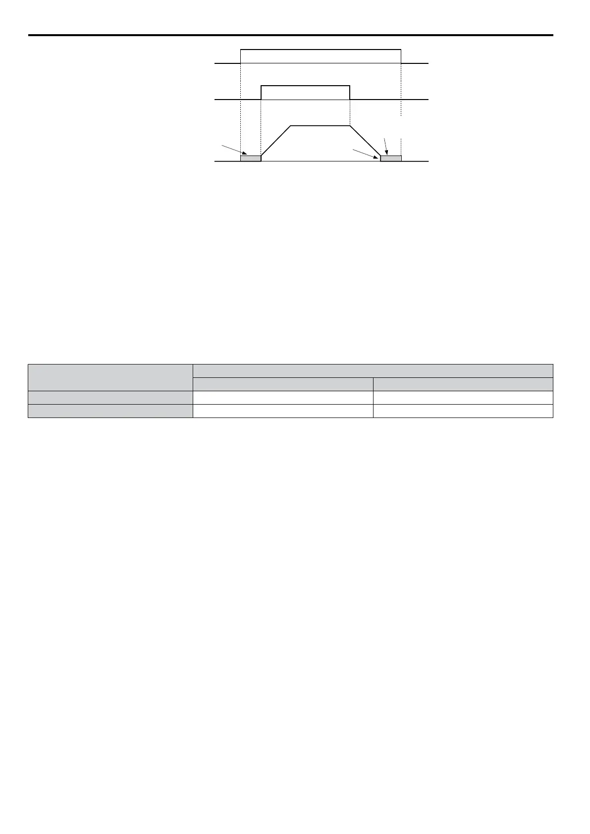
DC Injection braking
command
FWD Run command
Output frequency
DC Injection
braking
DC Injection
braking
DC Injection Braking
Start Frequency
(b2-01)
OFF
OFF OFF
OFFON
ON
Figure 5.54 DC Injection Braking Input Timing Diagram
Setting 61/62: Speed Search 1/2
These input functions can be used to enable Speed Search even if parameter b3-01 = 0 (no Speed Search at start. Refer
to Activation of Speed Search on page 127 for details on how to use the input signals.
If b3-24 is set to 0 and b3-01 is set to 0, when the input terminal set for Speed Search 1 (H1-oo = 61) is enabled, Speed
Search will begin looking for the motor speed from the maximum output frequency. If the Speed Search 2 input (H1-
oo = 62) is enabled, Speed Search starts looking for the motor speed starting at the frequency reference. Refer to b3:
Speed Search on page 125 for more information about Speed Search.
Note: Operator error oPE03 will result if both Speed Search 1 and Speed Search 2 are set to the input terminals at the same time.
Setting 65/66: KEB Ride-Thru 1 (N.C.)/2 (N.O.)
A digital input programmed for this function can be used to activate the KEB 1 function and detect power supply return.
Description
Digital Inputs
Setting 65 (N.C.) Setting 66 (N.O.)
KEB 1 deceleration Open Closed
Normal operation Closed Open
Refer to Kinetic Energy Backup (KEB) Function on page 208 for details on how to use these input settings.
Setting 67: Communication Test Mode
The drive has a built-in function for self-diagnosing the serial communications operation. The test involves wiring the
send and receive terminals of the RS-485/RS-422 port together. The drive transmits data and then confirms the
communications are received normally. Refer to Self-Diagnostics on page 430 for details on how to use this function.
Setting 68: High Slip Braking
Closing an input programmed for this function triggers
High Slip Braking. Once HSB is started, the drive has to completely
stop and the HSB input has to be removed before a restart can be performed. Refer to n3: High Slip Braking (HSB)/
Overexcitation Deceleration on page 230 for details on High Slip Braking.
Setting 6A: Drive Enable
A digital input configured as a Drive Enable input (H1-oo = 6A) will prevent the drive from executing a Run command
until the input is closed. When the Drive Enable input is open, the digital operator will display “dnE” to indicate that the
drive is disabled.
If a Run command is closed prior to the Drive Enable input being closed, then the drive will not run until the Run command
is cycled. If the Drive Enable input is opened while the drive is running, the drive will stop using the method set by
parameter b1-03 (Refer to b1-03: Stopping Method Selection on page 120 for details).
Setting 75/76: Up/Down 2
The Up/Down 2 function can be used to add a bias to the frequency reference. The input programmed for 75 will increase
the bias and the input programmed for 76 will decrease it. Table 5.26 explains how the Up/Down 2 function works
depending on the frequency reference source and parameters d4-01, d5-03 and d4-05. Refer to d4: Frequency Hold and
Up/Down 2 Function on page 156 for detailed explanations of these and other Up/Down 2 related parameters.
Note: 1. The Up 2 and Down 2 functions must be set as a pair.
2. When using the Up/Down 2 function, set appropriate bias limit values in parameters d4-08 and d4-09.
5.7 H: Terminal Functions
184
YASKAWA ELECTRIC SIEP C710606 16C YASKAWA AC Drive – V1000 Technical Manual

 Loading...


