n
E5-09: Motor Induction Voltage Constant 1 (PM OLV)
Set the induced phase peak voltage in units of 0.1 mV/(rad/s) [electrical angle]. Set this parameter when using an SSR1
series IPM motor with derated torque or an SST4 series motor with constant torque.
When E5-01 is set to “FFFF” use either E5-09 or E5-24 for setting the voltage constant.
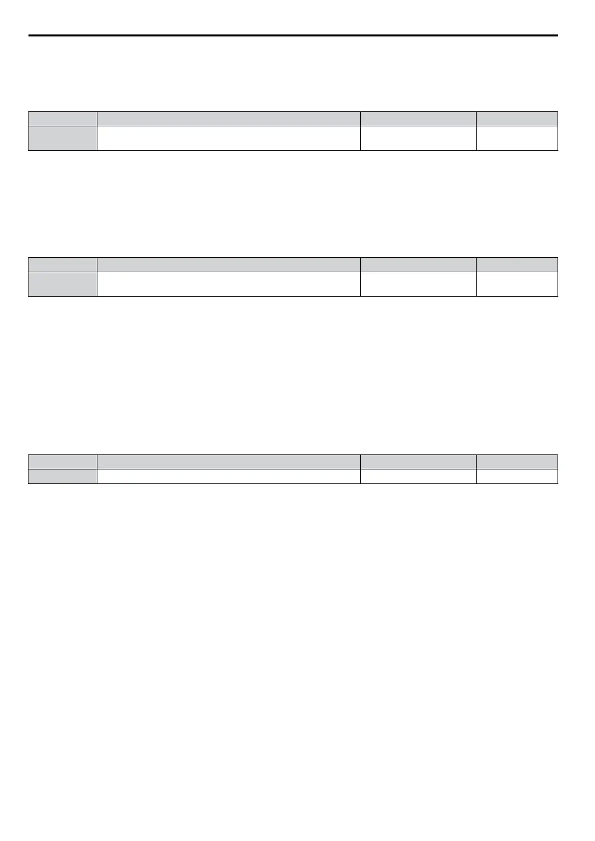
No. Parameter Name Setting Range Default
E5-09 Motor Induction Voltage Constant 1 0.0 to 2000.0 mV/(rad/s)
Depending on
E5-01
Note: 1. Ensure that E5-24 = 0 when setting parameter E5-09. An alarm will be triggered, however, if both E5-09 and E5-24 are set 0, or if
neither parameter is set to 0.
2. This parameter is not reset when the drive is initialized using A1-03.
n
E5-24: Motor Induction Voltage Constant 2 (PM OLV)
Set the induced phase-to-phase rms voltage in units of 0.1 mV/(r/min) [mechanical angle]. Set this parameter to 0 when
using an SMRA Series SPM Motor.
When E5-01 is set to “FFFF” use either E5-09 or E5-24 for setting the voltage constant.
No. Parameter Name Setting Range Default
E5-24 Motor Induction Voltage Constant 2 (PM OLV)
<1>
Depending on
E5-01
<1> Range depends on the drive software version.
PRG: 1018 and later: 0.0 to 6500.0 mV/(r/min)
PRG: 1017 and earlier: 0.0 to 2000.0 mV/(r/min)
Note: 1. If E5-03 is not set to 0, then setting both E5-09 and E5-24 to 0, or setting neither E5-09 nor E5-24 to 0, will trigger an oPE08 error.
However, if E5-03 is set to 0, setting both E5-09 and E5-24 to 0 will not trigger the error.
2. This parameter is not reset when the drive is initialized using A1-03.
3. The values for the electrical and mechanical angle should be set using the same units specified by the manufacturer of the motor.
n
E5-39: Current Detection Delay Time
Sets the current detection delay time of d-Axis and q-Axis current feedback calculation.
Changing this parameter from the default setting is not normally required.
Note: Parameter available in drive software versions PRG: 1022 and later.
No. Parameter Name Setting Range Default
E5-39 Current Detection Delay Time
-1000 to 1000 µs 0 µs
5.5 E: Motor Parameters
172
YASKAWA ELECTRIC SIEP C710606 16C YASKAWA AC Drive – V1000 Technical Manual

 Loading...


