Setting 1: Match Frequency Reference and Motor Speed
Note: In V/f control the drive ignores the value set to L4-08 and refers to the soft-starter output to determine whether a speed agreement
situation has been reached.
The following functions are influenced by the speed agree condition:
• Overtorque alarms oL3 and oL4 when parameters L6-01 or L6-04 are set to 1, 3, 5, or 7.
• DriveWorksEZ functions that use speed agree output
• The Up 2/Down 2 functions
• Multi-Function Digital Output Settings
Setting Value Function
2 Frequency (Speed) Agree 1
3 User-set Frequency (Speed) Agree 1
4 Frequency (FOUT) Detection 1
5 Frequency (FOUT) Detection 2
13 Frequency (Speed) Agree 2
14 User-set Frequency (Speed) Agree 2
15 Frequency (FOUT) Detection 3
16 Frequency (FOUT) Detection 4
• MEMOBUS/Modbus Monitor Data
Register No. Description
002CH
Drive Status 2
Bit 2 Speed Agree, 1: During Agree
Bit 3 User-set Speed Agree, 1: During Agree
Bit 4 Frequency Detection 1, 1: Output Frequency ≤ L4-01
Bit 5 Frequency Detection 2, 1: Output Frequency ≥ L4-01
004BH
Drive Status (U1-12)
Bit 4 1: During Speed Agree
• U: Monitor
No. Name Description
U1-12 Drive Status The fifth digit from the right side: During Speed Agree
n
Notes on Controlling the Brake for the Hoist Application
The frequency detection function is used for controlling the brake.
When
an external Baseblock command is present while
a Run command is active, the frequency reference will be kept as
long as the Run command is active. To avoid improper brake operation make sure that frequency detection is set so that
the brake does not open during Baseblock (L4-07 = “0”, default).
Brake Open/Close Brake Activation Level
Function Parameter Signal Parameter
Frequency
Detection
Conditions
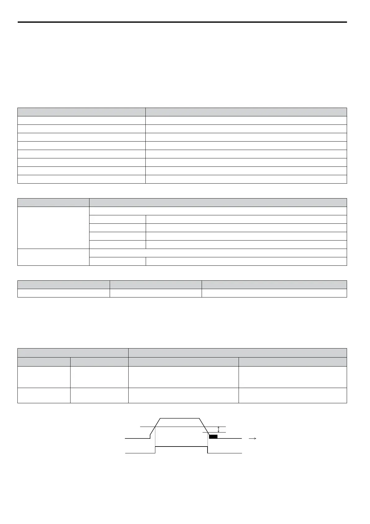
L4-07 = 0 Frequency Detection Level
L4-01 = 2.0 to 3.0 Hz
<1>
Frequency
Detection 2
H2-01 = 5 Frequency Detection Width 2.0 Hz (fixed)
<1> If the load slips during stop, make it greater than E1-09 or 2.0 Hz until the load no longer slips.
2.0 Hz (fixed)
L4-01
OFF
ON
Time
Output
Frequency
Frequency
Dectection 2
Figure 5.86 Frequency Detection 2
The braking sequence should be designed as follows:
• A normally open signal (N.O.) should be used to control the brake so that it is released when terminal MA-MC closes.
5.8 L: Protection Functions
218
YASKAWA ELECTRIC SIEP C710606 16C YASKAWA AC Drive – V1000 Technical Manual

 Loading...


