• An external circuit should be added to ensure the brake is fully applied in case of a fault or emergency condition.
• An additional external circuit should also be added
to ensure the brake releases properly when an Up/Down Command
is entered.
When changing the speed using an analog signal, make sure that the source of the frequency reference is assigned to the
control circuit terminals (b1-01 = 1).
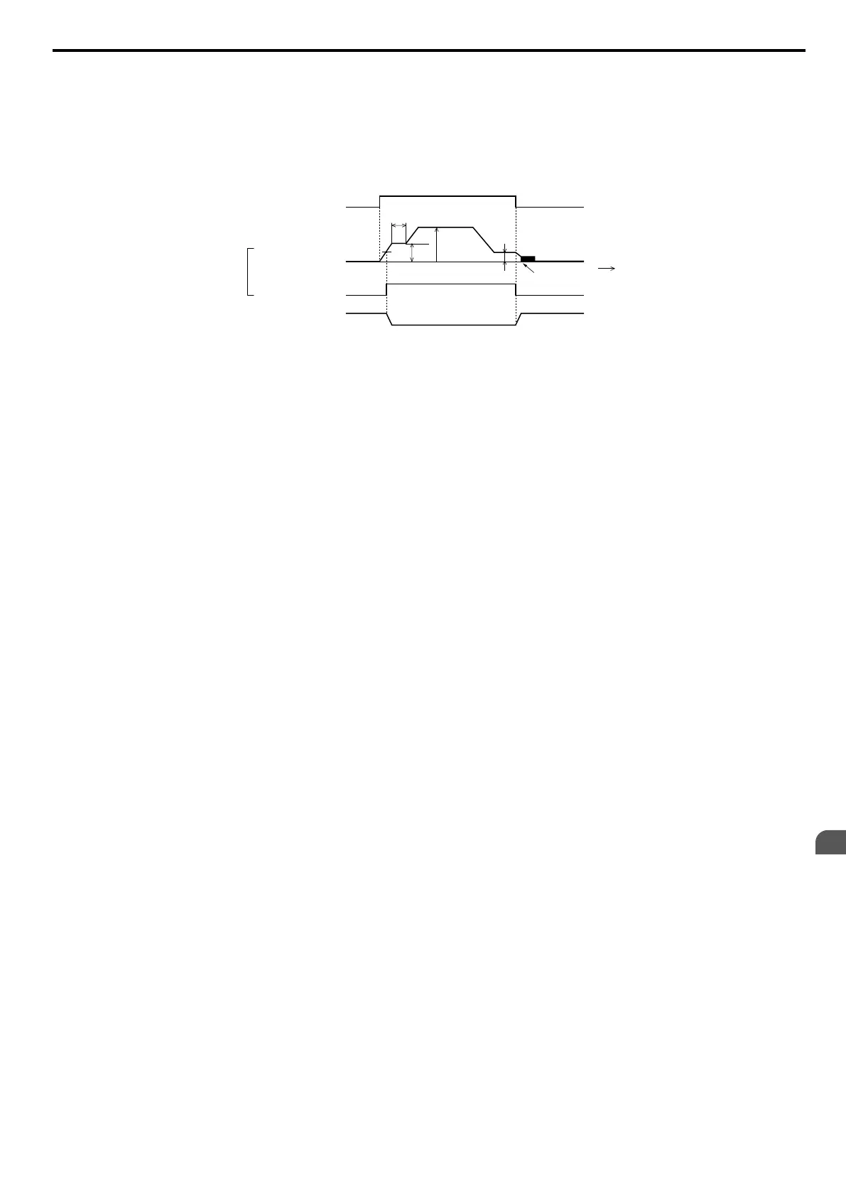
A sequence to open and close the holding brake appears in the diagram below.
Time
UP
S1-SC
OFF
d1-03
d1-01 (Enabled when b1-01 = 0)
L4-01
b4-01
OFF
DC Injection braking
ON
ON
MA-MC
Holding brake
Output frequency
0
Frequency Detection 2
(H2-01=5)
Closed Closed
Open
b6-02
b6-01
Output
Figure 5.87 Holding Brake Time Chart
5.8 L: Protection Functions
YASKAWA ELECTRIC SIEP C710606 16C YASKAWA AC Drive – V1000 Technical Manual
219
5
Parameter Details

 Loading...


