No. Name Description Range Def.
Control
Mode
Addr.
Hex
Pg.
V/
f
O
L
V
P
M
C6-01 Drive Duty Selection
Selects the load rating for the drive.
0: Heavy Duty (HD) for constant torque applications.
1: Normal Duty (ND) for variable torque applications.
This
setting affects the Rated output current and overload
tolerance of the drive.
0, 1 1 S S S 223 150
C6-02
Carrier Frequency
Selection
Selects the carrier frequency
1 : 2.0 kHz
2 : 5.0 kHz
3 : 8.0 kHz
4 : 10.0 kHz
5 : 12.5 kHz
6 : 15.0 kHz
7 : Swing PWM1 (Audible sound 1)
8 : Swing PWM2 (Audible sound 2)
9 : Swing PWM3 (Audible sound 3)
A : Swing PWM4 (Audible sound 4)
B: Leakage Current Rejection PWM
<3>
C to E: No setting possible
F : User defined (determined by C6-03 through C6-05)
<7> <8>
S S S 224 151
C6-03
Carrier Frequency Upper
Limit
Note: Set C6-02 to F before setting C6-03.
Open Loop Vector: C6-03 defines the fixed carrier
frequency if C6-02 = F.
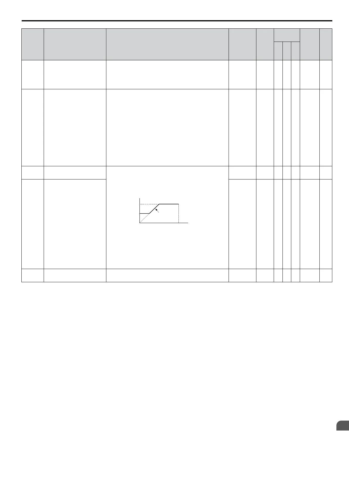
V/f Control: C6-03 and C6-04 set upper and
lower limits
for the carrier frequency.
carrier frequency
E1-04
max output
frequency
output frequency
× (C6-05) × K
output
frequency
C6-03
C6-04
The coefficient K depends on C6-03:
C6-03 ≥ 10.0 kHz: K = 3
10.0 kHz > C6-03 ≥ 5.0 kHz: K = 2
5.0 kHz > C6-03: K = 1
When C6-05 ≤ 6, C6-04 is disabled (makes the carrier
frequency C6-03 value).
1.0 to 15.0
<9>
A A A 225 151
C6-04
Carrier Frequency Lower
Limit
1.0 to 15.0
<9>
A - - 226 151
C6-05
Carrier Frequency
Proportional Gain
Sets the relationship of output frequency to carrier
frequency when C6-02 = F.
00 to 99
<9>
A - - 227 151
<1> Parameter can be changed during run.
<2> Setting range value is dependent on parameter C1-10, Accel/Decel Time Setting Units. When C1-10 = 0 (units of 0.01 seconds), the setting
range becomes 0.00 to 600.00 seconds.
<3> Available in drive software versions PRG: 1020 and later.
<4> Default setting value is dependent on parameter A1-02, Control Method Selection. The value shown is for A1-02 = 0-V/f Control.
<5> Parameter cannot be changed during run when parameter A1-02 = 5-PM OLV Control.
<6> Default setting value is dependent on parameter A1-02, Control Method Selection. The value shown is for A1-02 = 2-OLV control.
<7> Setting range is determined by the drive software version.
PRG: 1020 and later: 1 to B; F
PRG: 1018 and earlier: 1 to A; F
<8> Default setting value is dependent on parameters o2-04, Drive Model Selection, A1-02, Control Method Selection and C6-01, Drive Duty
Selection.
<9>
Default setting value is dependent on parameter C6-02, Carrier Frequency Selection.
B.2 Parameter Table
YASKAWA ELECTRIC SIEP C710606 16C YASKAWA AC Drive – V1000 Technical Manual
339
B
Parameter List

 Loading...


