n
Single Drive Installation
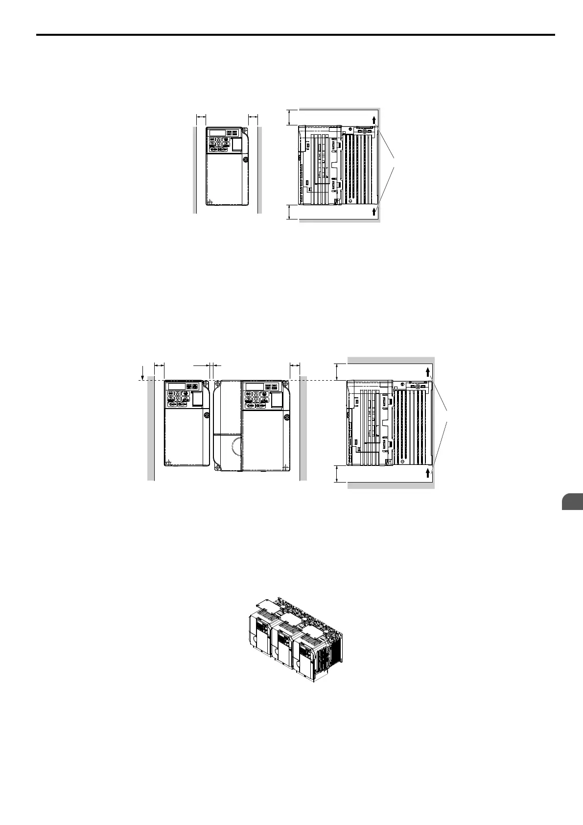
Figure 2.2
shows the required installation spacing to maintain
sufficient space for airflow and wiring. Install the heatsink
against a closed surface to avoid diverting cooling air around the heatsink.
A A
B
C
C
Top/Bottom Clearance
Side Clearance
A – 30 mm minimum
B – Airflow direction
C – 100 mm minimum
Figure 2.2 Correct Installation Spacing
Note: IP20/NEMA
Type 1, IP00/Open-Chassis,
and IP20/Open-Chassis models require
the same amount of space above and below the drive
for installation.
n
Multiple Drive Installation
When installing multiple drives into the same enclosure panel, mount the drives according to Figure 2.2. When mounting
drives with a minimum side-by-side clearance of 2 mm according to Figure 2.3, derating must be considered and parameter
L8-35 must be set. Refer to Parameter List on page 329.
A – Line up the tops of the drives.
B – 30 mm minimum
C – 100 mm minimum
D – Airflow direction
Figure 2.3 Space Between Drives (Side-by-Side Mounting)
Note: When
installing
drives
of
different
heights
in
the
same enclosure panel, the tops of the drives should line up. Leave space between the
top and bottom of stacked drives for cooling fan replacement if required. Using this method, it is possible to replace the cooling fans
later.
NOTICE: When mounting IP20/NEMA Type 1 enclosure drives side by side, the top covers of all drives must be removed as shown in
Figure 2.4.
Figure 2.4 IP20/NEMA Type 1 Side-by-Side Mounting in Enclosure
2.2 Mechanical Installation
YASKAWA ELECTRIC SIEP C710606 16C YASKAWA AC Drive – V1000 Technical Manual
39
2
Mechanical Installation

 Loading...


