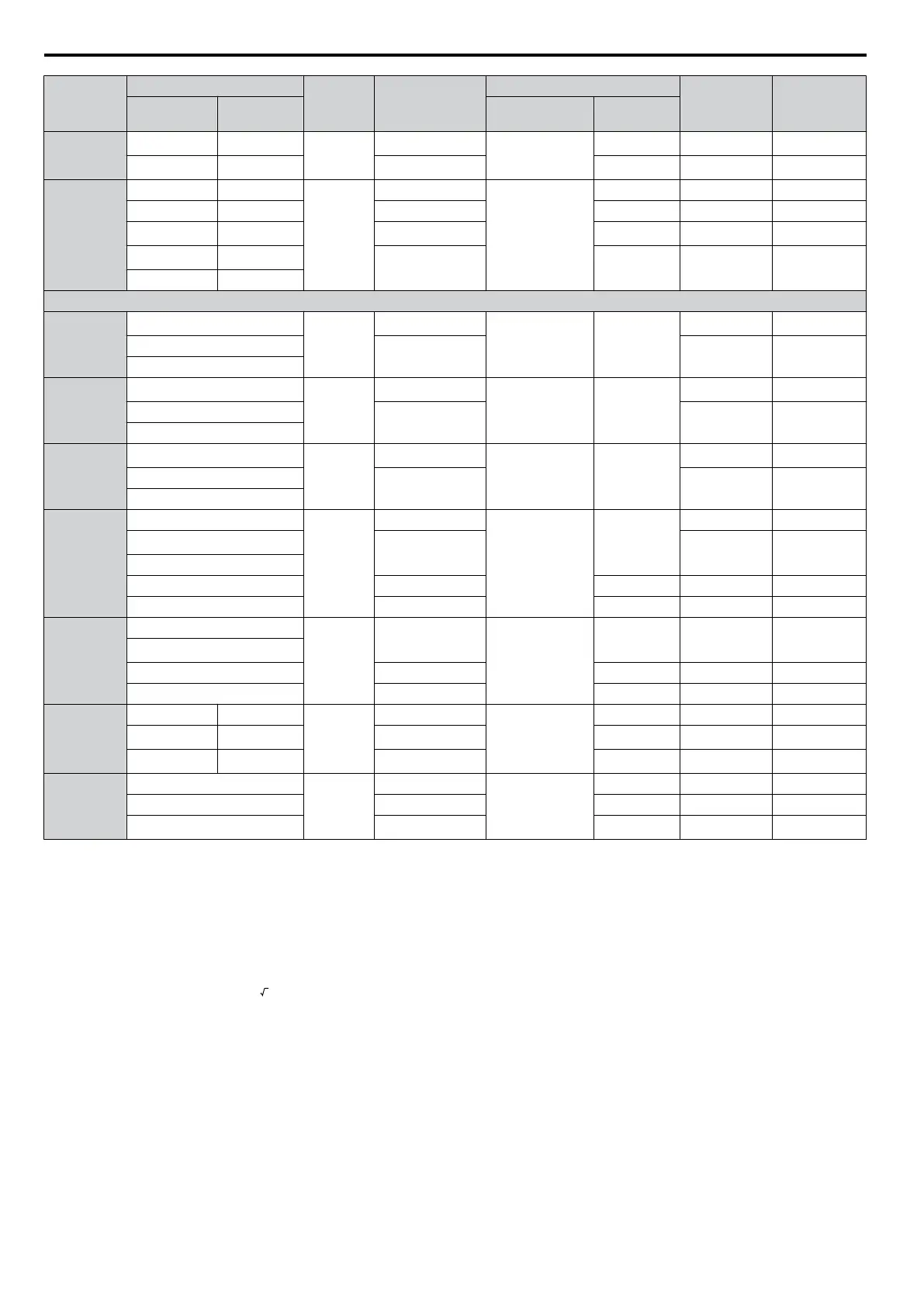
Drive Model
Wire Gauge AWG
Terminal
Screws
Crimp Terminal
Model No.
Tool
Insulation Cap
Model No.
Code
<2>
R/L1, S/L2,
T/L3
U/T1, V/T2,
W/T3
Machine No. Die Jaw
2A0056
6
6
<1>
M6
R14-6
YA-5
AD-952 TP-014 100-051-261
4
<1>
4 R22-6 AD-953 TP-022 100-051-262
2A0069
8 8
M8
R8-8
YA-5
AD-951 TP-008 100-061-111
6 6 R14-8 AD-952 TP-014 100-054-035
4
4
<1>
R22-8 AD-953 TP-022 100-051-263
3
<1>
3
R38-8 AD-954 TP-038 100-051-264
2 2
400 V Class Single-Phase Drives
4A0001
4A0002
4A0004
14
<1>
M4
R2-4
YA-4 AD-900
TP-003 100-054-028
12
R5.5-4 TP-005 100-054-029
10
4A0005
4A0007
4A0009
14
<1>
M4
R2-4
YA-4 AD-900
TP-003 100-054-028
12
R5.5-4 TP-005 100-054-029
10
4A0011
14
<1>
M4
R2-4
YA-4 AD-900
TP-003 100-054-028
12
R5.5-4 TP-005 100-054-029
10
4A0018
14
M4
R2-4
YA-4
AD-900
TP-003 100-054-028
12
<1>
R5.5-4 TP-005 100-054-029
10
8 8-4 AD-901 TP-008 100-054-031
6 14-4 AD-902 TP-014 100-066-220
4A0023
12
M4
R5.5-4
YA-4
AD-900 TP-005 100-054-029
10
<1>
8 8-4 AD-901 TP-008 100-054-031
6 14-4 AD-902 TP-014 100-066-220
4A0031
10 10
M5
R5.5-5
YA-4
AD-900 TP-005 100-054-030
8
8
<1>
R8-5 AD-901 TP-008 100-054-032
6
<1>
6 R14-5 AD-902 TP-014 100-054-034
4A0038
10
M5
R5.5-5
YA-4
AD-900 TP-005 100-054-030
8 R8-5 AD-901 TP-008 100-054-032
6
<1>
R14-5 AD-902 TP-014 100-054-034
<1> Recommended wire gauge.
<2> All codes in the far right column of the table above refer to a set including three crimp terminals and three insulation caps. Input and output
wiring must be prepared by the user. Two sets should be used for each terminal connection.
Example: Drive model BA0001 with 14 AWG for both input and output should use one set for input and one set for output. The user should
therefore order a total of two sets of [100-066-218].
Note: Consider the amount of voltage drop when
selecting wire gauges. Increase the wire gauge when the voltage drop is greater than 2% of
motor rated voltage. Ensure the wire gauge is suitable for the terminal block. Use the following formula to calculate the amount of
voltage drop:
Line drop voltage (V) =
3 × wire resistance (Ω/km) × wire length (m) × current (A) × 10
-3
D.3 UL Standards
446
YASKAWA ELECTRIC SIEP C710606 16C YASKAWA AC Drive – V1000 Technical Manual

 Loading...


