No. Name
User
Setting
E4-08
Motor 2 Motor Iron-Core Saturation
Coefficient 2
E4-09 Motor 2 Mechanical Loss
E4-10 Motor 2 Iron Loss
E4-11 Motor 2 Rated Capacity
E4-12 Motor 2 Iron-Core Saturation Coefficient 3
E4-14 Motor 2 Slip Compensation Gain
E4-15 Torque Compensation Gain - Motor 2
E5-01 Motor Code Selection (PM motor)
E5-02 Motor Rated Capacity (PM motor)
E5-03 Motor Rated Current (PM motor)
E5-04 Motor Poles (PM motor)
E5-05 Motor Stator Resistance (PM motor)
E5-06 Motor d Axis Inductance (PM motor)
E5-07 Motor q Axis Inductance (PM motor)
E5-09
Motor Induction Voltage Constant 1 (PM
motor)
E5-24
Motor Induction Voltage Constant 2 (PM
motor)
E5-39 Current Detection Delay Time
F1-02
Operation Selection at PG Open Circuit
(PGO)
F1-03
Operation Selection at Overspeed (OS) (for
Simple PG V/f)
F1-04
Operation Selection at Deviation (for Simple
PG V/f Control)
F1-08
Overspeed Detection Level (for Simple PG V/
f Control)
F1-09
Overspeed Detection Delay Time (for Simple
PG V/f Control)
F1-10
Excessive Speed Deviation Detection Level
(for Simple PG V/f Control)
F1-11
Excessive Speed Deviation Detection Delay
Time (for Simple PG V/f Control)
F1-14
PG Open-Circuit Detection Time (for Simple
PG V/f Control)
F6-01 Communications Error Operation Selection
F6-02 External Fault from Comm. Option Selection
F6-03
External Fault from Comm. Option Operation
Selection
F6-04 Trace Sampling Rate
F6-07 NetRef/ComRef Function Selection
F6-08 Reset Communication Parameters
F6-10 CC-Link Node Address
F6-11 CC-Link Communications Speed
F6-14 BUS Error Auto Reset
F6-20 MECHATROLINK Station Address
F6-21 MECHATROLINK Frame Size
F6-22 MECHATROLINK Link Speed
F6-23 MECHATROLINK Monitor Selection (E)
F6-24 MECHATROLINK Monitor Selection (F)
F6-25
Operation Selection at MECHATROLINK
Watchdog Timer Error (E5)
F6-26 MECHATROLINK bUS Errors Detected
F6-30 PROFIBUS-DP Node Address
F6-31 PROFIBUS-DP Clear Mode Selection
F6-32 PROFIBUS-DP Map Selections
F6-35 CANopen Node ID Selection
No. Name
User
Setting
F6-36 CANopen Communication Speed
F6-40 CompoNet Node ID
F6-41 CompoNet Speed
F6-50 DeviceNet MAC Address
F6-51 DeviceNet Communication Speed
F6-52 DeviceNet PCA Setting
F6-53 DeviceNet PPA Setting
F6-54 DeviceNet Idle Mode Fault Detection
F6-56 DeviceNet Speed Scaling
F6-57 DeviceNet Current Scaling
F6-58 DeviceNet Torque Scaling
F6-59 DeviceNet Power Scaling
F6-60 DeviceNet Voltage Scaling
F6-61 DeviceNet Time Scaling
F6-62 DeviceNet Heartbeat Interval
F7-01 Ethernet IP Address 1
F7-02 Ethernet IP Address 2
F7-03 Ethernet IP Address 3
F7-04 Ethernet IP Address 4
F7-05 Subnet Mask 1
F7-06 Subnet Mask 2
F7-07 Subnet Mask 3
F7-08 Subnet Mask 4
F7-09 Gateway Address 1
F7-10 Gateway Address 2
F7-11 Gateway Address 3
F7-12 Gateway Address 4
F7-13 Address Mode at Startup
F7-14 Security Password
F7-15 Duplex Mode Selection
F7-18 Communication Speed Selection
F7-19 Web Page Access
F7-20 Gateway Selection
F7-21 Communication Loss Time Out
H1-01
Multi-Function Digital Input Terminal S1
Function Selection
H1-02
Multi-Function Digital Input Terminal S2
Function Selection
H1-03
Multi-Function Digital Input Terminal S3
Function Selection
H1-04
Multi-Function Digital Input Terminal S4
Function Selection
H1-05
Multi-Function Digital Input Terminal S5
Function Selection
H1-06
Multi-Function Digital Input Terminal S6
Function Selection
H1-07
Multi-Function Digital Input Terminal S7
Function Selection
H2-01
Terminal MA, MB and MC Function
Selection (relay)
H2-02
Terminal P1 Function Selection (open-
collector)
H2-03
Terminal P2 Function Selection (open-
collector)
H2-06 Watt Hour Output Unit Selection
H3-01 Terminal A1 Signal Level Selection
H3-02 Terminal A1 Function Selection
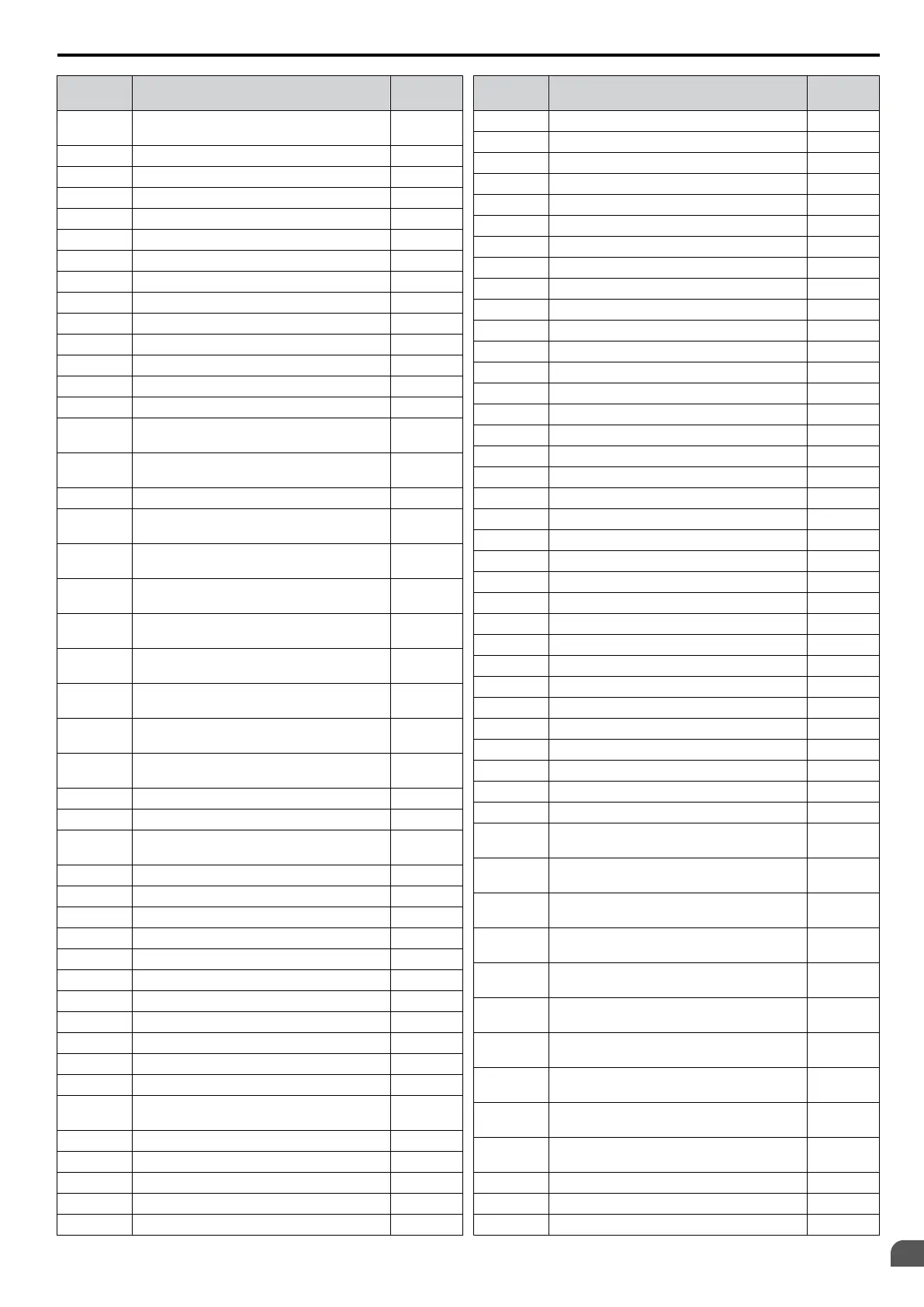
E.3 User Setting Table
YASKAWA ELECTRIC SIEP C710606 16C YASKAWA AC Drive – V1000 Technical Manual
459
E
Quick Reference Sheet

 Loading...


