<5. Functions>
83
IM 01E21A02-03EN
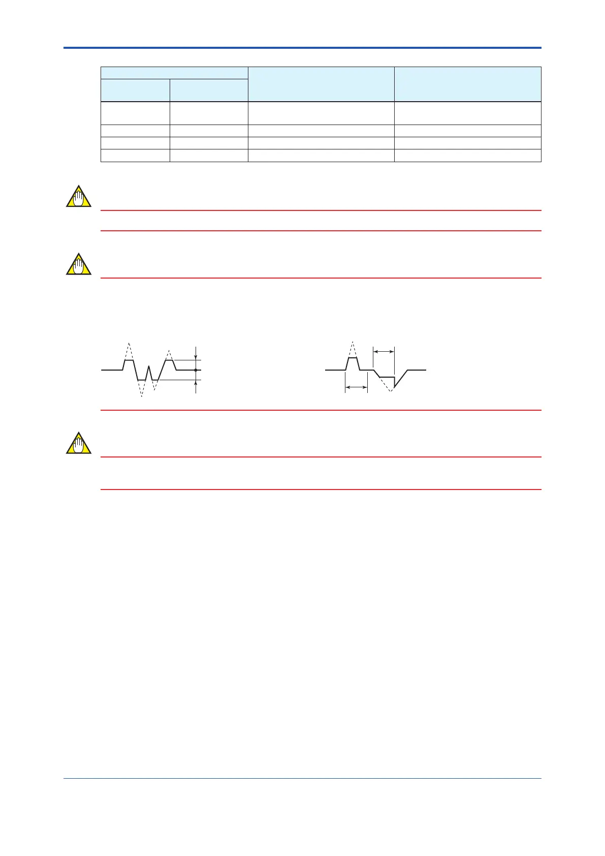
*1: Fromthetablebelow,selectthenoiselter(ratelimitvalueanddeadtime).
Selection
Rate limit value Dead time
Display
F
OUNDATION
Fieldbus
Manual Manual
Thevalueisspeciedinthe
parameter“Ratelimit”.
Thevalueisspeciedinthe
parameter“Deadtime”.
Level 1 Level 1 0.5% 0.5s
Level 2 Level 2 1.0% 1.0s
Level 3 Level 3 5.0% 3.0s
NOTE
Ifeithertheratelimitvalueorthedeadtimeisspecied,thenoiselterissetto“Manual”.
NOTE
Determining the rate limit value and dead time
T
0
T
0
2%
2%
The Rage limit value:
Determine the level which should be cut the output
fluctuation. For example, if its level is 2%, the noise of 2%
or larger would be cut as shown in the following figure.
The Dead time (T
0
Determine the value depending on the width of the output
fluctuation. Choose the larger value when the noise which is
over the dead time as shown in the following figure.
NOTE
Fortheratelimitfunction,thedeadtimeissetto“0”atshipmentfromthemanufacturingfactory.
Be sure to set the dead time when the rate limit function is used.
Signal processing for rate limit function
Theproductcalculatestosetthespecicratelimitvaluetotheprimarydelayresponsevalueof
thepreviouslysampledowratevalue.Iftheowratevaluesampledatthistimeexceedsthe
ratelimitvalueabove,itshighorlowlimitissettotheowratevalueatthistime.Furthermore,
if the sampling count occurs within the dead time while the signal over the high/low limit is in the
samedirection,thissignalisjudgedtobeaowratesignal.

 Loading...


