<5. Functions>
84
IM 01E21A02-03EN
Example:
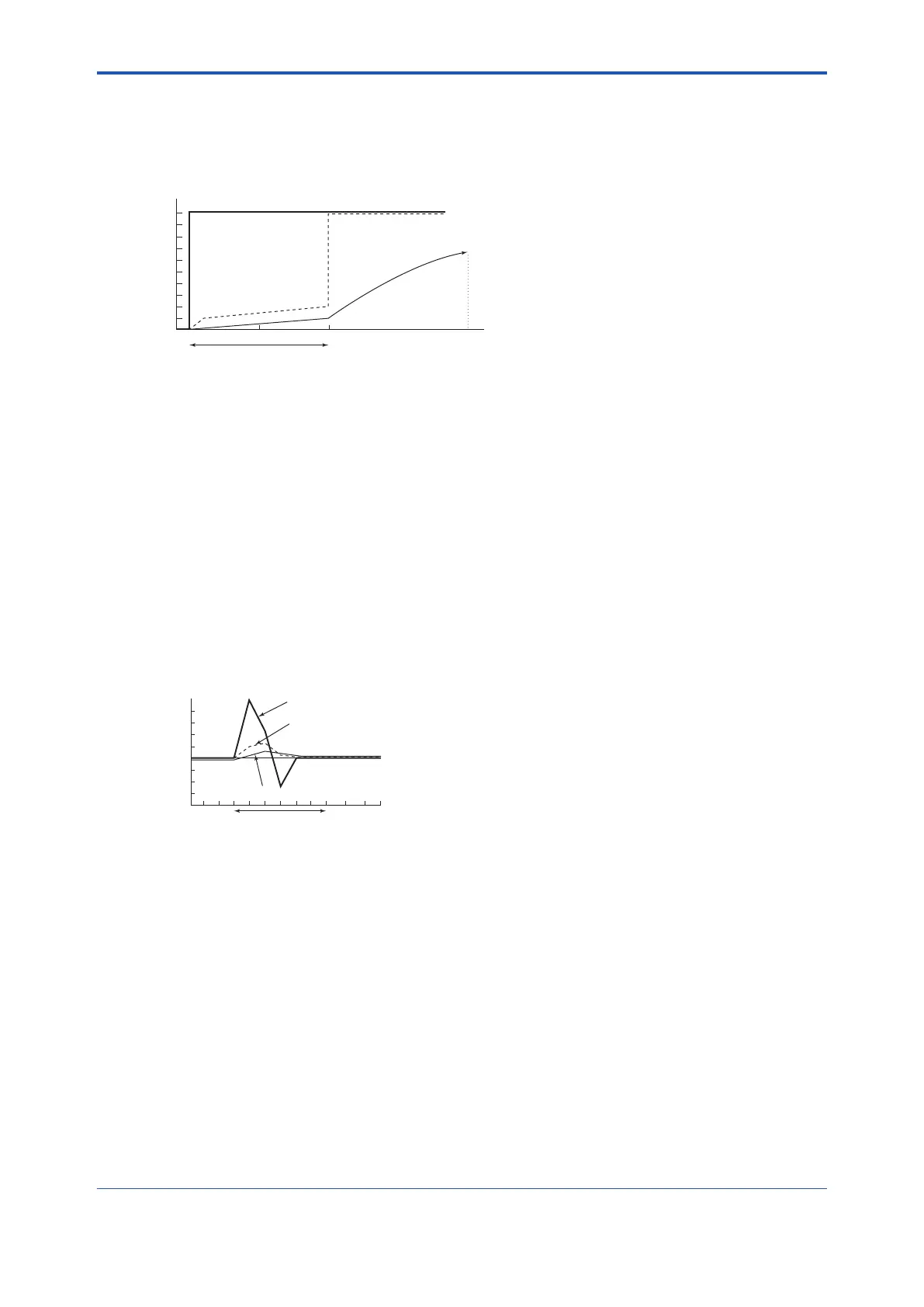
(1) Wheninput=0to10%,Dampingtimeconstant=5seconds,Deadtime=3seconds,
andRatelimitvalue=1%,theoutputforthestepinputisobtainedasshownbelow.
1%
Step signal
Flow rate value
after rate limit
processing
100 225
(a)
(b)
(c)
(d) Flow rate value
after damping
Damping time constant: 5 s
Dead time: 3 s
Rate limit value: 1%
Number of signal samples
• Intheconditionabove(1),thesignalexceedstheratelimitvalueascomparedwiththe
previous value; therefore, the response is set to 1%.
The actual output, which is damped, is processed as indicated with the solid line.
• Then,theowratevalueinthedeadtimeissettothe“owrateafterdampingcalculation+
signalofratelimitvalue(1%)”.
• The input signal does not return to the rate limit value or less within the dead time; therefore,
itisjudgedtobeaowratesignalatthetimeof(3).
• The output signal starts following the step signal along the damping curve.
Thegurebelowshowsanoutputexamplewhenaslurrynoiseoccurs.
(2) Wheninput=0to10%,Dampingtimeconstant=1second,Deadtime=1seconds,
andRatelimitvalue=1%,theoutputforaslurrynoiseisobtainedasshownbelow.
F0422.ai
+1%
-1%
Dead time: 1 s
Flow rate value after damping
Flow rate value
after rate limit
processing
Slurry noise
Time
Input: 0 to 10%
Damping time constant: 1 s
Dead time: 1 s
Rate limit value: 1%
In the figure on the left,
it is determined that the
slurries noise signal is
not a flow rate signal.

 Loading...


