2-31
IM MW100-01E
Installation and Wiring
2
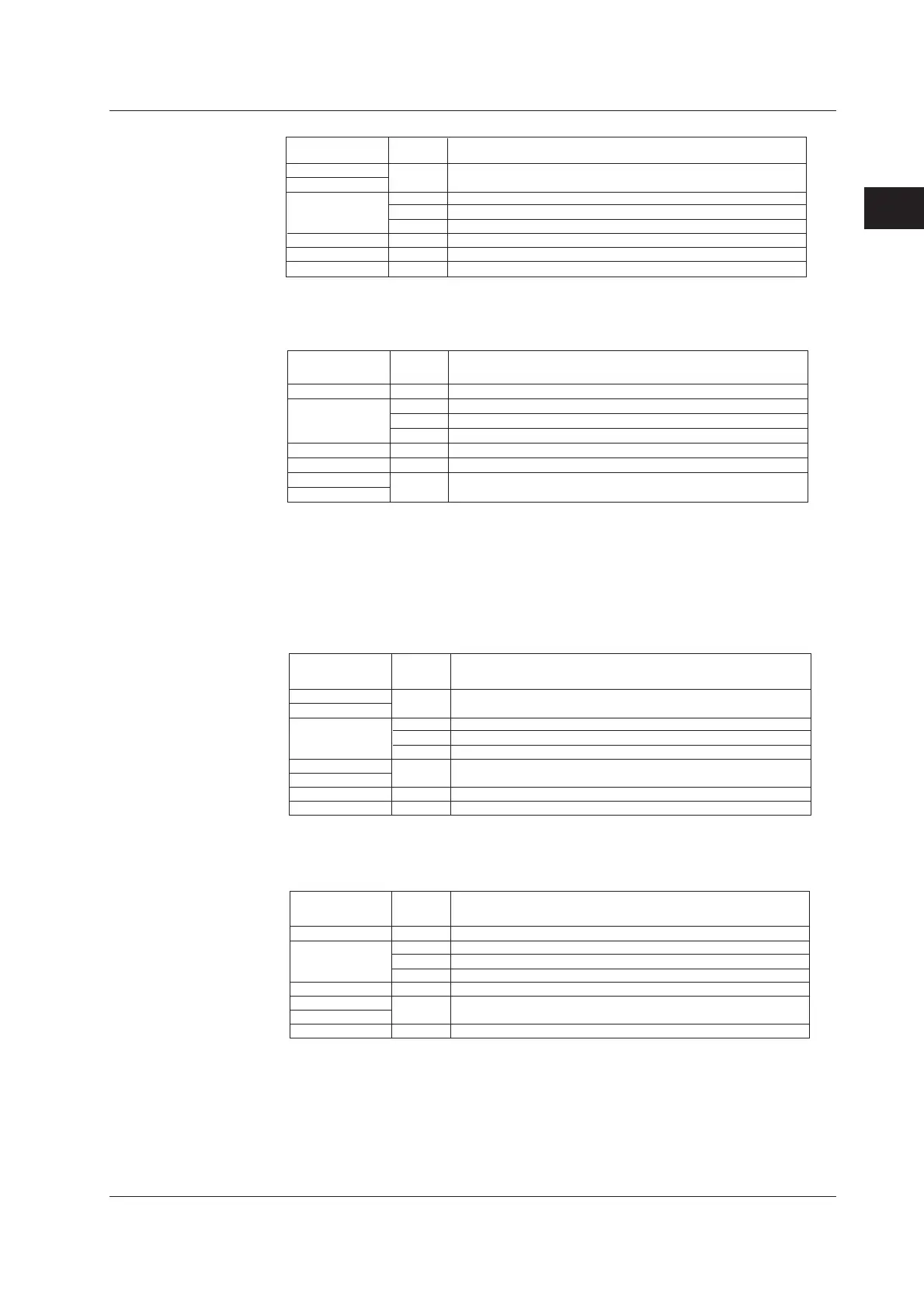
Measurement
Interval
100 ms
16.67 ms
20 ms
Auto
Integration
Time
Rejected Frequencies and Notes
500 ms
1 s
2 s
5, 10, 20, 30, 60 s
36.67 ms
100 ms
200 ms
600 Hz and its integer multiples*
60 Hz and its integer multiples
50 Hz and its integer multiples
Automatically detects the power supply frequency and set 16.6 or 20 ms
50 Hz and 60 Hz and their integer multiples
10 Hz and its integer multiples
200 ms
1.67 ms
6-CH, Medium-Speed 4-wire RTD Resistance Input Module/10-CH, Middle-Speed Universal Input Module
Low-pass filter with Fc = 5 Hz
* Because the power supply frequency noise is not rejected, measured values may fluctuate particularly for temperature
measurements using thermocouples. If this happens, make the measurement interval longer, or use the 4-CH High-Speed
Universal Input Module.
Measurement
Interval
Integration
Time
Rejected Frequencies and Notes
4-CH, Medium-Speed Strain Input Module
100 ms
200ms
500 ms
1 s
2 s
5, 10, 20, 30,60 s
1.67 ms
16.67 ms
20 ms
Auto
36.67 ms
100 ms
200 ms
600 Hz and its integer multiples*
60 Hz and its integer multiples
50 Hz and its integer multiples
Automatically detects the power supply frequency and set 16.67 or 20 ms
50 Hz and 60 Hz and their integer multiples
10 Hz and its integer multiples
Low-pass filter with Fc = 5 Hz
* When the measurement interval is 100 ms, measured values may fluctuate since power supply frequency
noise is not rejected.
In such cases, set the measurement interval to 200 ms or more.
However, when using the SNTP time synchronization function, the integral times below
are used.
Measurement
Interval
100 ms
16.67 ms
20 ms
Auto
Integration
Time
Rejected Frequencies and Notes
500 ms
1 s
2 s
5 s
10, 20, 30, 60 s
36.67 ms
100 ms
200 ms
600 Hz and its integer multiples*
60 Hz and its integer multiples
50 Hz and its integer multiples
Automatically detects the power supply frequency and set 16.6 or 20 ms
50 Hz and 60 Hz and their integer multiples
10 Hz and its integer multiples
Low-pass filter with Fc = 5 Hz
200 ms
1.67 ms
6-CH, Medium-Speed 4-wire RTD Resistance Input Module/
10-CH, Middle-Speed Universal Input Module
* Because the power supply frequency noise is not rejected, measured values may fluctuate particularly
for temperature measurements using thermocouples. If this happens, make the measurement interval
longer, or use the 4-CH High-Speed Universal Input Module.
Measurement
Interval
100 ms
1.67 ms
16.67 ms
20 ms
Auto
Integration
Time
Rejected Frequencies and Notes
200 ms
500 ms
1 s
2 s
5, 10, 20, 30, 60 s
36.67 ms
100 ms
200 ms
600 Hz and its integer multiples*
60 Hz and its integer multiples
50 Hz and its integer multiples
Automatically detects the power supply frequency and set 16.6 or 20 ms
50 Hz and 60 Hz and their integer multiples
10 Hz and its integer multiples
Low-pass filter with Fc = 5 Hz
4-CH, Medium-Speed Strain Input Module
* When the measurement interval is 100 ms, measured values may fluctuate since power supply frequency
noise is not rejected.
In such cases, set the measurement interval to 200 ms or more.
2.9 Measures Against Noise on the MW100 Data Acquisition Unit

 Loading...