2-32
IM MW100-01E
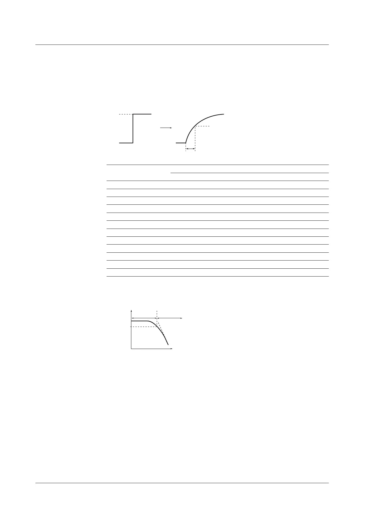
First-Order Lag Filter
For noise sources other than power supply noise, the MW100 Data Acquisition Unit is
equipped with a first-order lag filter having output characteristics indicated in the figure
below against step input.
For the filter setting, the time constant is determined by selecting filter coefficient N for
the measurement interval.
Step input
63.2% of the output value
Time constant
0%
100%
Output characteristics
Filter coefficient = measurement interval x filter coefficient N
Measurement Interval (s) Selectable Time Constants (s)
N=5 N=10 N=20 N=25 N=40 N=50 N=100
0.01 0.05 0.1 0.2 0.25 0.4 0.5 1
0.05 0.25 0.5 1 1.25 2 2.5 5
0.1 0.5 1 2 2.5 4 5 10
0.2 1 2 4 5 8 10 20
0.5 2.5 5 10 12.5 20 25 50
1 5 10 20 25 40 50 100
2 10 20 40 50 80 100 200
5 25 50 100 125 200 250 500
10 50 100 200 250 400 500 1000
20 100 200 400 500 800 1000 2000
30 150 300 600 750 1200 1500 3000
60 300 600 1200 1500 2400 3000 6000
If the first-order lag filter is applied to the input signal, low-pass filter frequency
characteristics shown in the figure below are attained.
Cutoff band
0dB
–3dB
Pass band
Frequency
Attenuation
Cutoff frequency
If the time constant of the first-order lag filter is set long, the cutoff frequency is lowered,
and frequency bandwidth that can be rejected is widened. Set an appropriate time
constant according to the frequency of the noise you wish to reject.
2.9 Measures Against Noise on the MW100 Data Acquisition Unit

 Loading...