5-37
IM MW100-01E
Specification
5
Noise rejection: Rejection by the integrating A/D converter and the use of low pass
fi lters
Input resistance: For DC voltage 1 V range or less: 10 MΩ or less
For DC voltage 2 V range or higher: Approx. 1 MΩ
Insulation resistance: Between input terminal and earth terminal: 20 MΩ or more (500
VDC)
Input bias current: 10 nA or less
Withstand voltage: 1000 VACrms (50/60 Hz) for one minute between input terminals
(DC voltage and DI)
620 VACrms (50/60 Hz) for one minute between input terminals
(RTD and resistance)
3700 VACrms (50/60 Hz) for one minute between the input
terminal and earth terminal
Input signal source resistance:
DC voltage: 2 kΩ or less
Resistance and RTD ranges: 10 Ω or less per line (same for all
ranges)
Shunt capacity: 0.01 µF or less (when using RTD and resistance ranges)
Power consumption: Approx. 1.2 W
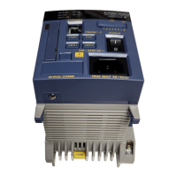
External dimensions: Approx. 57 (W) × 131 (H) × 151 (D) mm (including the terminal
cover)
Weight: Approx. 0.5kg.
Terminal type: Clamp, terminal board is detachable
Applicable wire size: 0.14 to 1.5 mm
2
(AWG26 to 16)
Effects of Operating Conditions
The specifi cations below apply when the integration time is 16.67 ms or more.
Warm-up time: At least 30 minutes after power-up
Effects of ambient temperature:
The effect received by changes in 10 degree increments of the
ambient temperature is ±(0.05% of rdg. + 0.05% of range) or less.
However, for Cu10 Ω: ±(0.2% of range + 1 digit)
Effects of power fl uctuation:
Meets the accuracy specifi cations for AC power supply in the
range 90 to 132 V and 180 to 250 V
Effects of magnetic fi eld: The fl uctuation in external magnetic fi elds for AC (50/60 Hz)
400 A/m is ±(0.1% of rdg. + 10 digits) or less
Effects from the signal source resistance: Effect from fl uctuation in DC voltage signal
source resistance of 1 kΩ
1 V range or less ±10 µV or less
2 V range or higher ±0.15% of rdg. or less
RTD: Fluctuation from 10 Ω change per line
1000 Ω, 100 Ω types: ± 0.1°C or less
Other than 1000 Ω, 100 Ω types: ± 1.0°C or less
Resistance: Fluctuation from 10 Ω change per line: ±1 digit or less
Effect of position: Horizontal with the feet at the bottom is the rule.
Effects of vibration: The fl uctuation that results by applying a sinusoidal vibration
along all three axes at a frequency between 10 to 60 Hz and an
acceleration of 0.2 m/s
2
is ±(0.1% of rdg. + 1 digit) or less
5.6 6-CH, Medium-Speed Four-Wire RTD Resistance Input Module Specifications

 Loading...