4-1
IM MW100-01E
Troubleshooting and Maintenance
4
Chapter 4 Troubleshooting and Maintenance
4.1 Error Display on the 7-Segment LED and
Corrective Actions
The main module has a two-digit 7-segment LED. The 7-segment LED displays the
system status. This section describes the displays on the 7-segment LED when errors
occur on the system and their corrective actions. For information about normal displays
other than for errors, see section 1.3, “Functions of the Main Module.”
If servicing is necessary, or if the instrument is not operating correctly after performing
the corrective actions below, contact your nearest YOKOGAWA dealer.
Errors upon Startup
The left and right digits of the 7-segment LED display “b” and an error code, respectively.
The LED illuminates.
Display Probable Cause Corrective Action Ref. section
b* (where * The dip switch settings Turn OFF the power, remove the CF card, turn ON all dip 1.3
is any character are not correct. switches, and power up again. If the situation does not change
other than F). servicing is required.
bF. The dip switch settings Powering up in setup reset mode. Turn OFF the power, turn ON 1.3
are not correct. all dip switches, and power up again. Since all settings such as
the IP address are initialized, reconfiguration is necessary.
System Errors
The left and right digits of the 7-segment LED display “F” and an error code, respectively.
The LED illuminates.
Display Possible Problem Corrective Action Ref. section
F0 System ROM error. Servicing required. -
F1 SRAM error Servicing required. -
F2 EEPROM error Servicing required. -
F3 Error in the internal battery Servicing required. -
of the main module. However, this error is also displayed immediately after the
battery is replaced. If this happens, power-cycle the MW100.
F4 Ethernet controller error Servicing required. -
F6 Web fi le load error Servicing required. -
FF Error in writing unit information Servicing required. -
Module Errors
The left and right digits of the 7-segment LED display are U and an error code,
respectively. The LED illuminates.
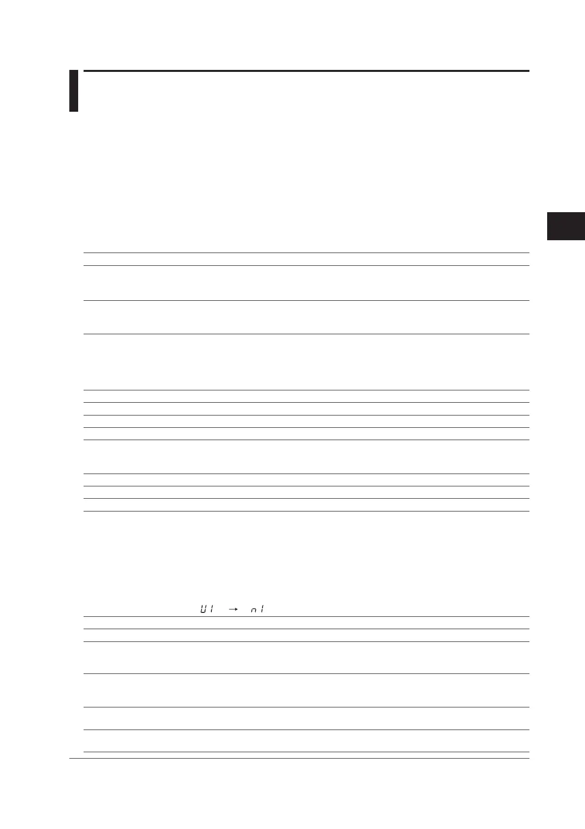
In the case of module errors, the error number and the corresponding module number
are displayed alternately as shown in the figure below.
Error number Module number
Display Possible Problem Corrective Action Ref. section
U0 Range information error. Servicing required. -
U1 Calibration value error. Check the module’s installation status, then recalibrate the -
module. If the error occurs even after recalibrating, servicing
is required.
U2 Calibration reference voltage Check whether the correct calibration reference voltage is -
value is not correct. being applied or whether the channel to which the voltage is
(during calibration) applied is correct.
U3 Error in writing the calibration Servicing required. -
value.
U4 The installed module cannot Replace the module with one that can be used. -
be used.

 Loading...