2-25
IM MW100-01E
Installation and Wiring
2
2.7 Connecting the RS-422A/485 Interface (/C3
Option)
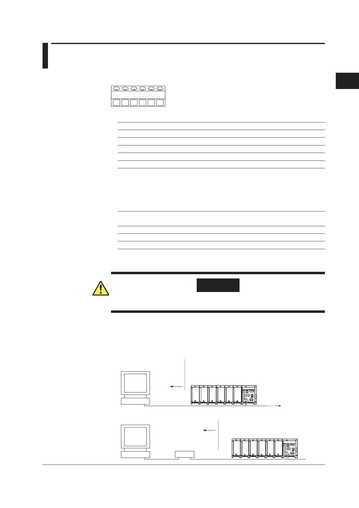
Terminal Wiring and Signal Names
SERIAL COMM
FG SDB SDA RDB RDASG
FG (Frame Ground) Case grounding for the main unit.
SG (Signal Ground) The signal ground.
SDB (Send Data B) Send data B(+).
SDA (Send Data A) Send data A(–).
RDB (Received Data B) Received data B(+).
RDA (Received Data A) Received data A(–).
Connection Procedure
Cables Used
There are two types of cable, a 4-wire and 2-wire cable. Choose a cable depending on
the following conditions.
Cable Used Twisted pair shielded cable
3 × 24 AWG or more (4-wire), 2 × 24 AWG or more (2-wire)
Characteristic impedance 100 Ω
Capacitance 50 pF/m
Cable length Max 1.2 km*
* The transmission distance of the RS-422A/485 interface is not the direct distance, but rather
the total cable length (shielded, twisted pair).
WARNING
To prevent electric shock, confirm that the power supply is turned OFF before
making connections.
Connections with Upstream Devices
The following figure shows a connection with an upstream device. If the upstream
devices use an RS-232 port, connect through a converter.
Main unit
RS-422A/485
terminals
Host computer
or connected
upstream instrument
Connected
upstream
instrument
Converter
RS-422A/485
MW100
Main unit
RS-422A/485
terminals
Host computer
RS-232
RS-422A/485
MW100
Connected upstream instrument

 Loading...