1-43
IM MW100-01E
Explanation of Functions
1
1.10 Functions of the 8-CH, Medium-Speed PWM
Output Module
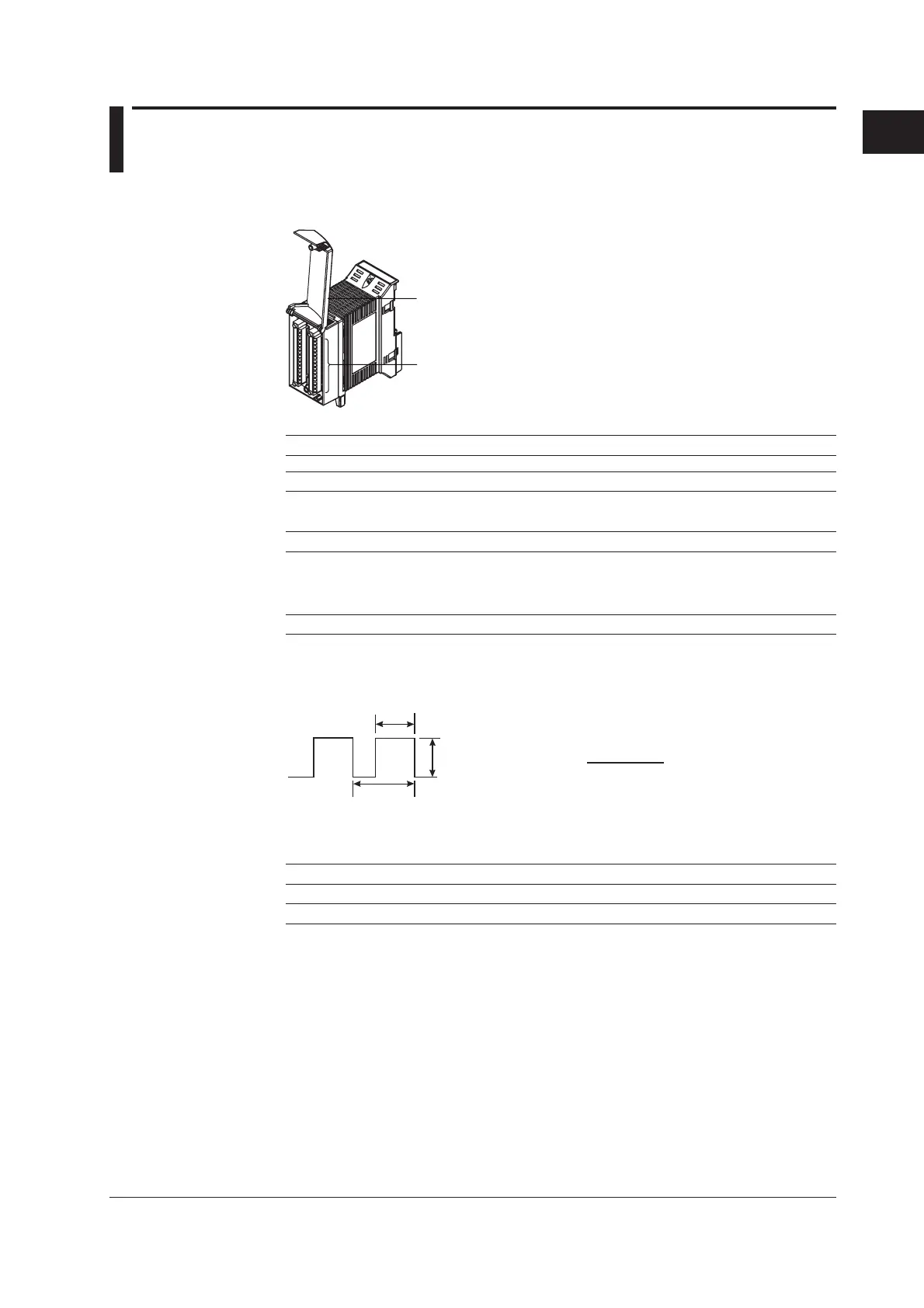
This module has eight outputs for pulse wave duty. A certain duty pulse waveform is output
according to the specified pulse interval. A pulse interval can be set for each channel.
Input terminal (clamp terminal)
Terminal cover
Output Types
Output Type Notation
No output SKIP
PWM Output PWM
Output Method
Output Method Notation Actions
Transmit TRANS Outputs a duty pulse wave according to the measured or
computed results of the input channel specified on the same
unit. You can also produce pattern output using the broken line
input function.
Arbitrary output COM Outputs specified data based on the values sent from the PC.
Output Range and Output Waveform
Output range: 0.000 to 100.000%
Pulse interval
Output width
External
power supply
voltage
Duty=
Output width
Pulse interval
×100 [%]
Pulse Interval
1 ms to 300 s (can be set channel by channel)
Range Notation Setting Range
1 ms interval setting range 1 ms 1 ms to 30.000 s (can be set in units of 1 ms)
10 ms interval setting range 10 ms 10 ms to 300.00 s (can be set in units of 10 ms)
* The pulse interval can be set by determining the pulse interval coefficient.
The pulse interval coefficient is set from 1 to 30000.
Pulse interval = range × pulse interval coefficient
Output Update Interval
The output is updated at 100-ms (minimum) intervals. It is not synchronized to the
measurement interval.
Operation upon Startup and Error Occurrence
See section 1.11, “Operation of the 8-CH Medium-Speed Analog Output Module and the
8-CH Medium Speed PWM Output Module.”

 Loading...