1-11
IM MW100-01E
Explanation of Functions
1
Connectors
The MW100 can come with the following connectors. The actually-installed connectors
depend on the power supply input section specifications and options.
• Ethernet
• RS-422A/485 connector (/C3 option)
• RS-232 connector (/C2 option)
• CF card slot
• Power supply inlet (power supply input section specification: -1M)
• Power supply screw terminals (power supply input section specification: -1W, -2M, -3W)
Displays
The MW100 indicates its operating conditions with the following displays.
• 7-segment LED
• Status indicators
• Communication status LED
7-Segment LED
Displays the MW100 Data Acquisition Unit’s unit number, operation status, end of
operation, and errors.
• Unit Number Display
Unit numbers can be set from 00 to 89.
- is displayed.
• Display of the Self-Test Operation on Startup
When the power is turned ON the setting of dip switch 1 is displayed
followed by
the operation preparation status
, and then a self check is performed. While the
self check is in progress, the following displays are repeated.
• Key Lock Status
A key lock function is included for preventing accidental manipulation of the MW100
front panel keys. The key lock status is indicated by a dot at the bottom of the unit
number. The example shown is for a unit of number 00.
Unit number and dotUnit number
• Keylock release • Keylock
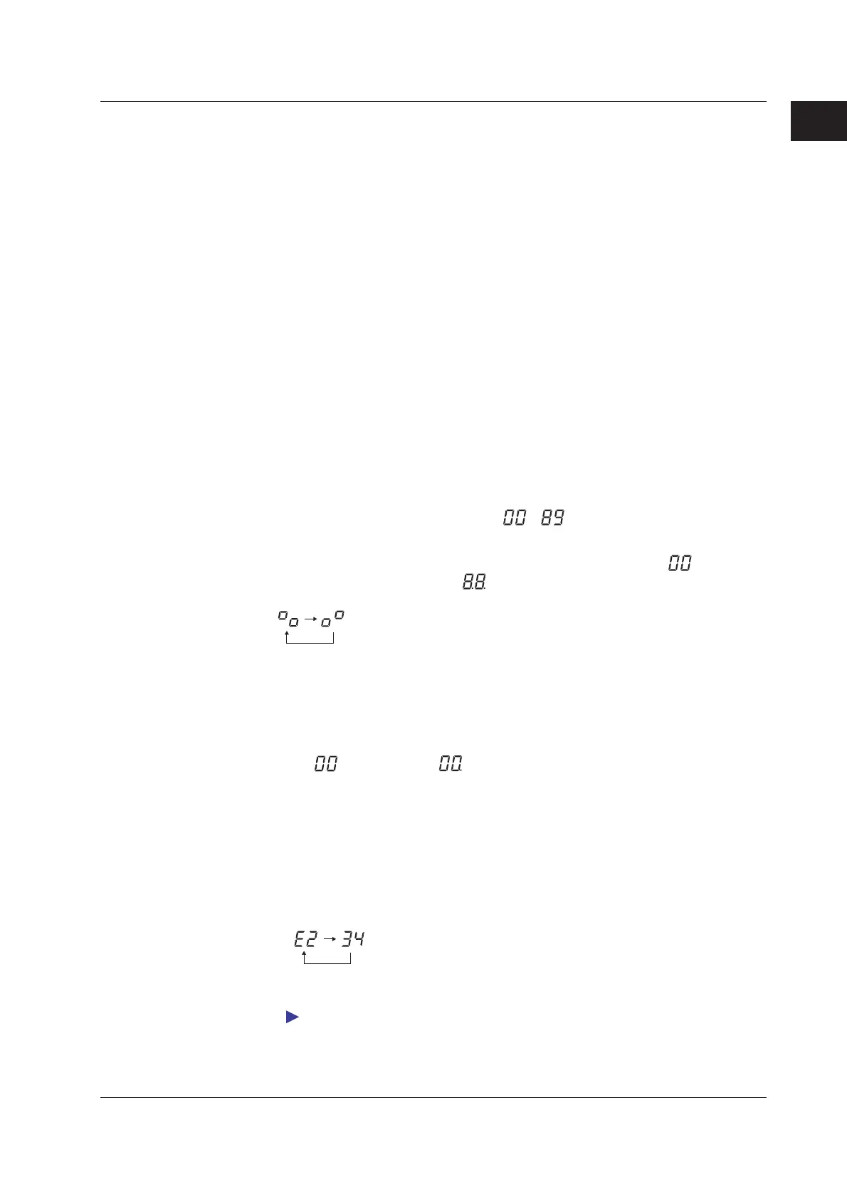
• Operation Error Display
In error Exxx (where xxx is a three-digit number), the code is divided into two parts
which are displayed alternately. In the first part, the letter E appears in the left digit
with the hundreds digit of the error code to the right, and the second part consists of
the last two digits of the error code.
Example: Error code E234
Up to three error codes are saved. You can clear one error that is displayed by
pressing the Stop key.
For the contents of error codes and their meanings, see section 4.1, “Errors Displayed on
the 7-Segment LED and Corrective Actions.”
1.3 Functions of the Main Module

 Loading...