3-25
IM MW100-01E
Setting and Data acquisiton
3
Global Channel Settings
If the setting items of channels are the same, the settings of the first channel can be
applied collectively to the specified range. The setting range of channels is 001 to 060.
Be sure to meet the following conditions for the specified range.
• The first channel number is a channel number of an input module.
• The last channel number is greater than the first channel number.
• Include at least one channel number on the input module.
• The channels between the first and the last channel numbers are input modules that
have been recognized by the system.
If the modules below are connected, you can set 001 to 016 but not 001-028, because
they contain output modules. However, if the input range is set to TC in 001-016, setting
is not possible, because Four-Wire RTD Resistance Input Module channels cannot be
set.
001-004 4-CH, High-Speed Universal Input Module
011-016 6-CH, Medium-Speed Four-Wire RTD Resistance Input Module
021-028 8-CH, Medium-Speed PWM Output Module
Procedure
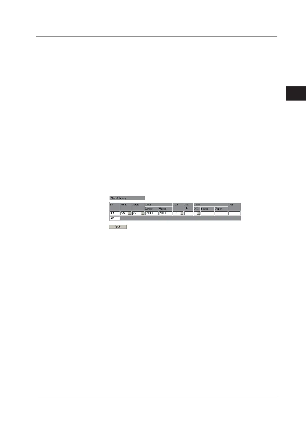
1.
Enter the first and last channel numbers of the modules you want to set
collectively. (The figure below is an example in which channels 001 to 004 are set
collectively.)
2.
The first number is set to the default value. Change the setting.
3.
Click the Apply button. The settings are applied to the specified range of
channels.
3.5 Setting Measurement Conditions indstop (indstart Measurement Channel Settings)

 Loading...