2-17
IM MW100-01E
Installation and Wiring
2
Wiring Digital Input Modules
Note
• With digital input modules, the (–) terminal and open terminals on all channels are shorted
internally.
• When the plate with screw terminal (model 772080) is connected to the Digital Input Module,
the terminal arrangement differs from that of clamp terminals, so wire according to the
markings on the terminal cover.
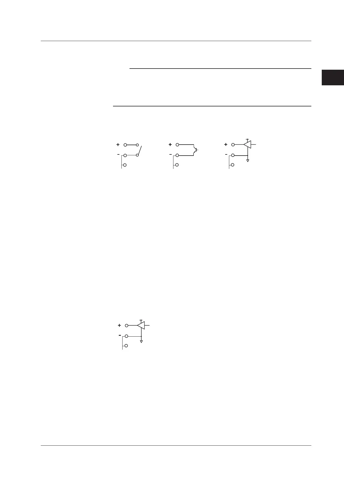
Wiring with the -D05 Option
• Transistor input
• Contact input
• 5V logic input
5V
Main Input Specifications (-D05)
Input type: DI (non-voltage contact, open collector, and 5-V logic)
Input format: Pull up at approx. 5 V/approx. 5 kΩ, common potential between
channels
Min. detection pulse width:
Twice the sampling interval or more
Input threshold level: Non-voltage contact, open collector: 100 Ω or less, ON, 100
kΩ or less, OFF
5-V logic: OFF at 1 V or less and ON at 3 V or greater
Contact/Transistor rating:
Contact with a rating of 15 VDC or greater and 30 mA or
greater
Transistor with a rating of Vce > 15 VDC and Ic > 30 mA
Terminal type: Clamp
Applicable wire size: 0.14 to 1.5 mm
2
(AWG26 to 16)
Wiring with the -D24 Option
24V
• 24 V logic input
Main Input Specifications (-D24)
Input type: DI (24-V logic)
Input format: Common potential between channels
Min. detection pulse width: Twice the sampling interval or more
Input threshold level: 24-V logic: OFF at 6 V or less and ON at 16 V or greater
Terminal type: Clamp
Applicable wire size: 0.14 to 1.5 mm
2
(AWG26 to 16)
2.4 Connecting Signal Wires

 Loading...