1-9
IM MW100-01E
Explanation of Functions
1
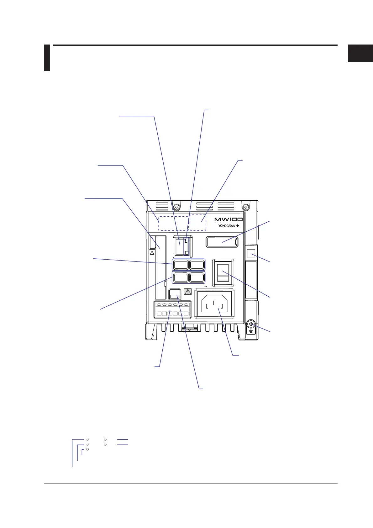
1.3 Functions of the Main Module
The main module is the central component of the MW100 Data Acquisition Unit.
Names and Functions of Parts
DATA ACQUISITION UNIT
MEASURE
RECORD
SERIAL RD
ETHERNET
10BASE - T
100BASE - TX
START
100 - 240V AC
STOP
USER 2USER 1
POWER
SW
ON
12 876543
MATH
ALARM
TERMN
ON
OFF
SERIAL COMM
FG SDB SDA RDB RDASG
70VA MAX 50 / 60Hz
MEASURE
RECORD
SERIAL RD
MATH
ALARM
7-segment LED
Displays the operational status of
the MW100 (see “Displays” in this
section, or section 4.1, “7-Segment
LED Error Display”).
Ethernet port
Used for main unit settings
and network connections
(see 2.6, “Connecting an
Ethernet Cable,” or 3.2,
“Connecting to the MW100.”)
Status indicator*
The operational status of the
instrument is indicated by the
illumination of the LED.
Communication status LED
Check the communication status
Top: LINK LED
Illuminates orange when ready for communication
Bottom: ACT LED
Blinks green when packets are sent/received
CF card slot
Insert the CF card to save
data and perform other tasks
(see section 2.11, “Handling of the
CF Card,” or 3.3, “System Settings”).
Terminator switch (/C3 option)
Turns the terminator ON and OFF
*Status indicators
Illuminate in the following situations. (See section 3.12, “Starting and Stopping Measurement,
Computation, and Recording.”)
Receiving serial communications data
Recording (illuminates), recording stop processing (blinking)
Measuring
Alarm activation or alarm hold
Computing (illuminates), computing stop processing (blinking)
RS-422A/485 connector (/C3 option)
Depending on installed options, the connector may
or may not be available, or it may be an RS-232
connector (/C2 option, see “Communication
Specifications” in this section)
Power supply inlet
Connect the accessory power supply
cord This is listed as a screw terminal
in the power supply specifications.
Functional ground
terminal
Power switch
Turns the power to the
MW100 main unit ON
and OFF
Dip switch 1
Used to initialize settings,
and for other purposes
(see, “Switches and
Keys” in this section)
Dip switch 2
Not used.
Start/Stop keys
Start and stop measurement,
computation, and recording
(seesection 3.12, “Starting and
Stopping Measurement, Computation,
and Recording”).
User function key
Assign functions to the keys
(see, “Switches and Keys” in this
section)

 Loading...