5-26
IM MW100-01E
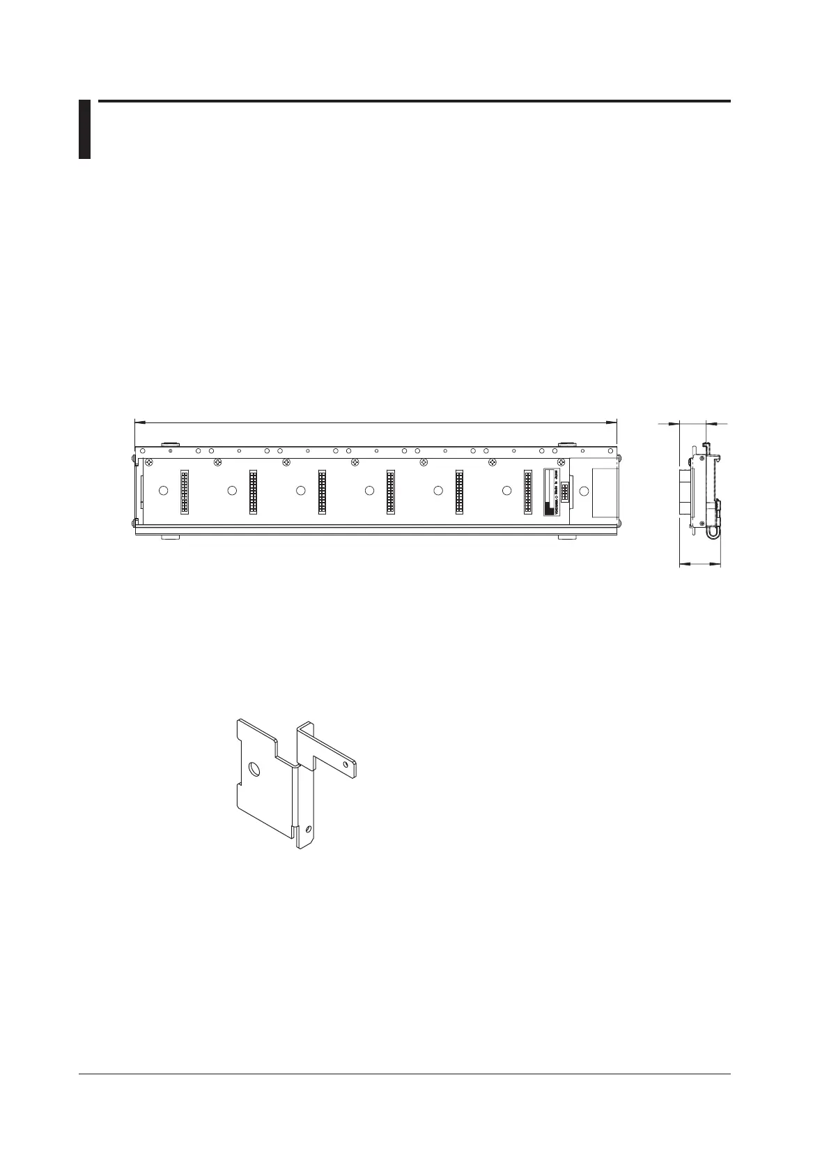
5.3 Base Plate Specifications
Number of main modules that can be attached:
1 (always attached)
Number of input/output modules that can be attached:
1 to 6 (specifi ed by the suffi x code)
External dimensions: Approx. 118 to 408 (W) × 75 (H) × 35 (D) mm
Weight: Approx. 0.37 kg (1 main module, for connecting six input/output
modules)
External Dimensions
Units: mm
22.5
34.6
MX150-1, -2, -3, -4, -5, -6
407.5 (1 main module, for connecting six input/output modules)
117.5 (1 main module, for connecting one input/output module)
58 pitches in between
If not specified, the tolerance is ±3%. However, in cases of less than 10 mm, the
tolerance is ±0.3 mm.
Attaching the MW100 Main Module
The accessory bracket must be attached in order to attach the MW100 main module
to the base plate. For information about attaching the bracket, see the Installation and
Connection Guide (IM MW100-72E).

 Loading...