2-28
IM MW100-01E
2.8 Connecting the RS-232 Interface (/C2 Option)
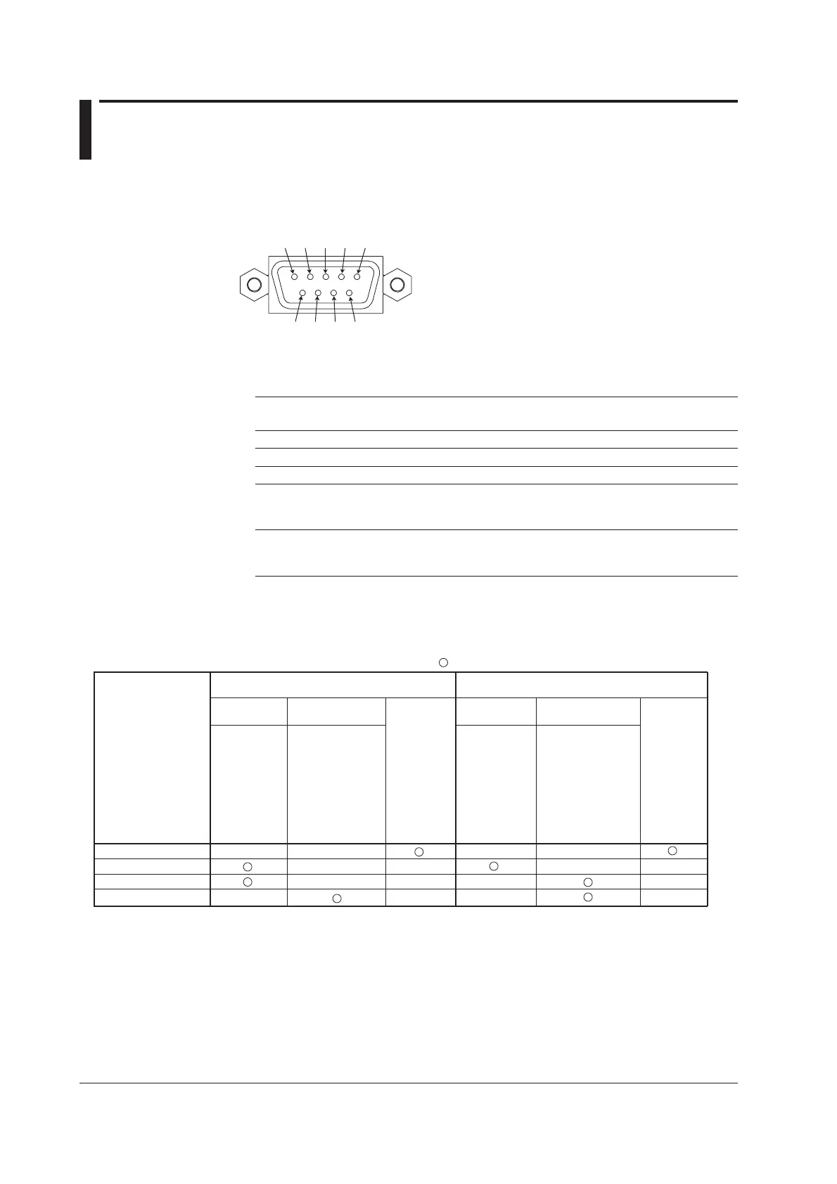
Connector Pin Assignments and Signal Names
Connector Pin Assignments
2
1
3
4 5
6
7
9
8
Signal Names Corresponding to Connector Pins
The following table shows signal names for the RS-232, JIS, and ITU-T standards.
Pin Signal Name Notation Meaning
JIS ITU-T RS-232
2 RD 104 BB (RXD) Receive data Input signal to the instrument
3 SD 103 BA (TXD) Transmitted data Output signal from the instrument
5 SG 102 AB (GND) Signal ground The signal ground.
7 RS 105 CA (RTS) Request to send The handshaking signal when receiving
data from the computer, and output signal
from the instrument.
8 CS 106 CB (CTS) Clear to send The handshaking signal when receiving
data from the computer, and input signal to
the instrument.
* Pins 1, 4, 6, and 9 are not used.
Handshaking
One of the following four methods in the table below can be selected for the instrument.
Data Transmission Control
(Control used to send data to a PC)
Data Reception Control
(Control used to receive data from a PC)
Software
handshaking
Software
handshaking
Table of Handshaking Methods ( indicates that it is supported)
OFF-OFF
XON-XON
XON-RS
CS-RS
Handshaking method
Stops
transmission
when X-OFF
is received.
Resume
when X-ON
is received.
Stops transmission
when CB (CTS)
is false.
Resume when
it is true.
No
handshaking
No
handshaking
Send X-OFF
when the
received data
buffer is 3/4th
filled. Send
X-ON when the
received data
buffer becomes
1/4th filled.
Set CA (RTS) to
False when the
received data buffer
is 3/4th filled. Set to
True when the
received data buffer
becomes 1/4th filled.
Hardware
handshaking
Hardware
handshaking
OFF-OFF
• Send Data Control
Handshaking is not performed between the instrument and the computer. “X-OFF” and
“X-ON” from the computer are treated as data, and CS is ignored.
• Receive Data Control
Handshaking is not performed between the instrument and the computer. When the
receive buffer of the instrument becomes full, data thereafter is discarded.
RS = True (fixed)

 Loading...