5-39
IM MW100-01E
Specification
5
5.7 4-CH, Medium-Speed Strain Input Module
Specifications
Style number: S2
Number of inputs: 4
Input type: Strain gauge or strain gauge type sensors (static strain)
Input method: Floating balanced input isolated between channels (NDIS is non-
isolated)
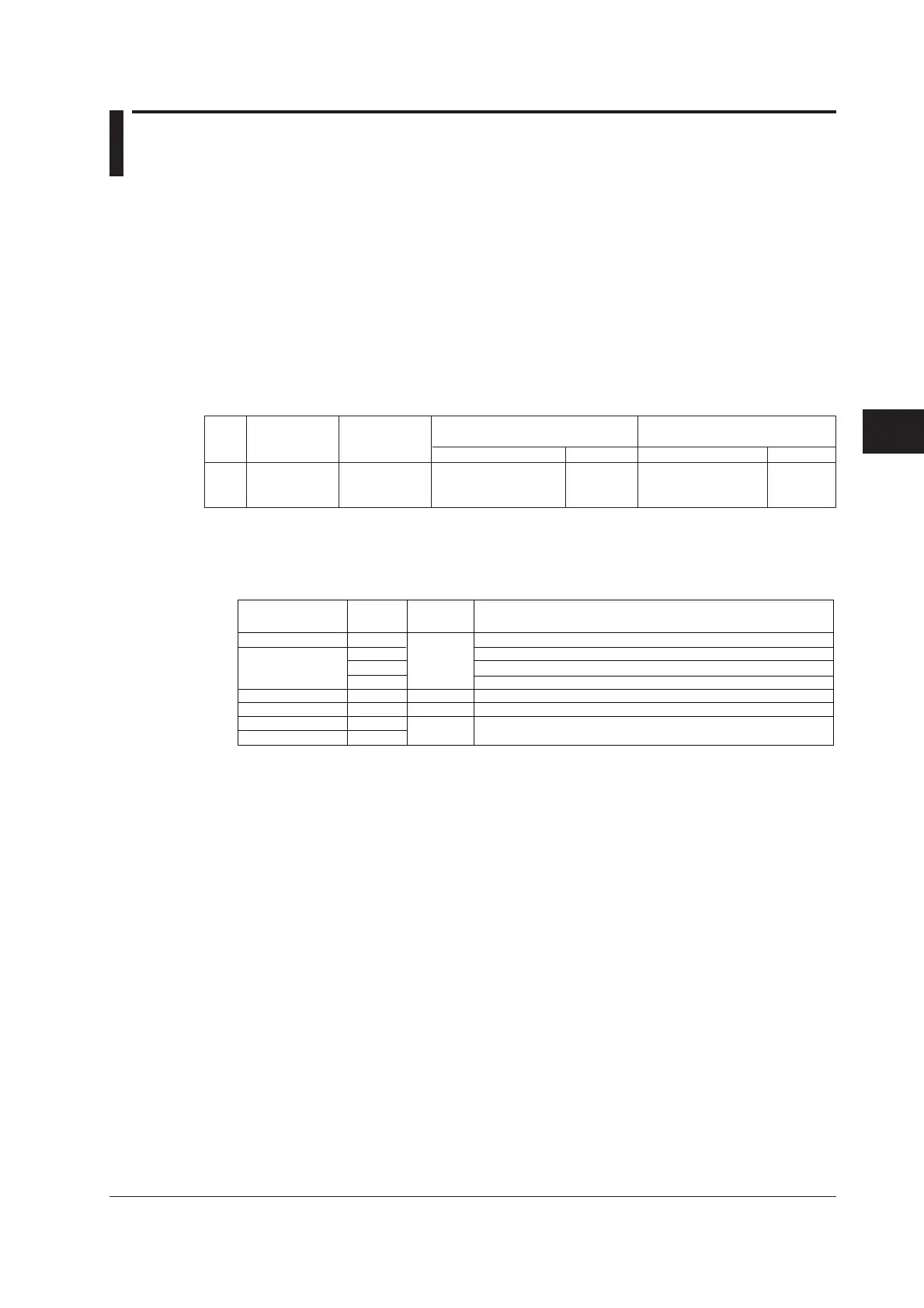
Measurement range and accuracy:
The accuracy applies to standard operating conditions:
Ambient temp: 23±2°C, ambient humidity: 55±10% RH, supply
voltage: 90 to 250 VAC, power frequency: 50/60 Hz ± 1%, warm-
up time: at least 30 minutes, without adverse conditions such as
vibrations.
One-Gauge Method Conversion
1 µStrain
2 µStrain
10 µStrain
0.1 µStrain
1 µStrain
10 µStrain
2% of range
1% of range
1% of range
±0.5% of range
±0.3% of range
±0.3% of range
*1
*2
2000 µStrain
20000 µStrain
200000 µStrain
Strain
±2000.0 µStrain
±20000 µStrain
±200000 µStrain
*1 Display resolution is 0.1 µStrain
*2 Display resolution is 1 µStrain
Measurement
Range
Type
Input
Rated
Measurement
Range
Resolution Resolution
Integration time:
16.67 ms or more
Integration time:
1.67 ms or more
Measurement Accuracy Measurement Accuracy
AD resolution: Equivalent to ± 20000 FS display
However, excludes 1.67 ms integration time
AD integration time:
Measurement
Interval
1.67 ms
16.67 ms
20 ms
Auto
2
36.67 ms
100 ms
200 ms
3
200 ms
Integration
Time
Filter
Rejected Noise and Notes
Rectangular
100 ms
200 ms
500 ms
1 s
2 s
5, 10, 20, 30, 60 s
Trapezoidal
Rectangular
Cos
600 Hz and its integer multiples
1
60 Hz and its integer multiples
50 Hz and its integer multiples
Automatically detects the power supply frequency and set 16.67 or 20 ms
50 Hz, 60 Hz and their integer multiples
10 Hz and its integer multiples
Fc = 5-Hz low-pass filter
1
When the measurement interval is 100 ms, measured values may fluctuate since power supply frequency
noise is not rejected. In such cases, set the measurement interval to 200 ms or more.
2
For DC power, set to 20 ms.
3
When synchronizing time by SNTP, the integral time is set to 100 ms. Also in this case, noise of 10 Hz and its integer
multiples is rejected.
Gauge connection method:
1-gauge (2 or 3 wire systems), opposing 2 gauge, adjacent 2- or
4-gauge
With clamp terminals, set on a channel basis with switches
Applicable gauge resistance: 100 to 1000 Ω
120 Ω for -B12; 350 Ω, built-in resistance for -B35
Bridge voltage: Fixed at 2 VDC. Accuracy ±5% compensated with internal Cal
Applicable gauge factor:
Fixed at 2.0. Gauge factor can be compensated with the scaling
function
Balance adjustment: Automatic, digital calculation methods
Balance adjustment range:
±10000 µstrain (1 gauge method conversion)
Balance adjustment accuracy:
The measurement accuracy or less
Resistance accuracy for bridge:
±0.01% ±5ppm/°C
Input resistance: 1 MΩ or more.

 Loading...