App-5
IM MW100-01E
Appendix
App
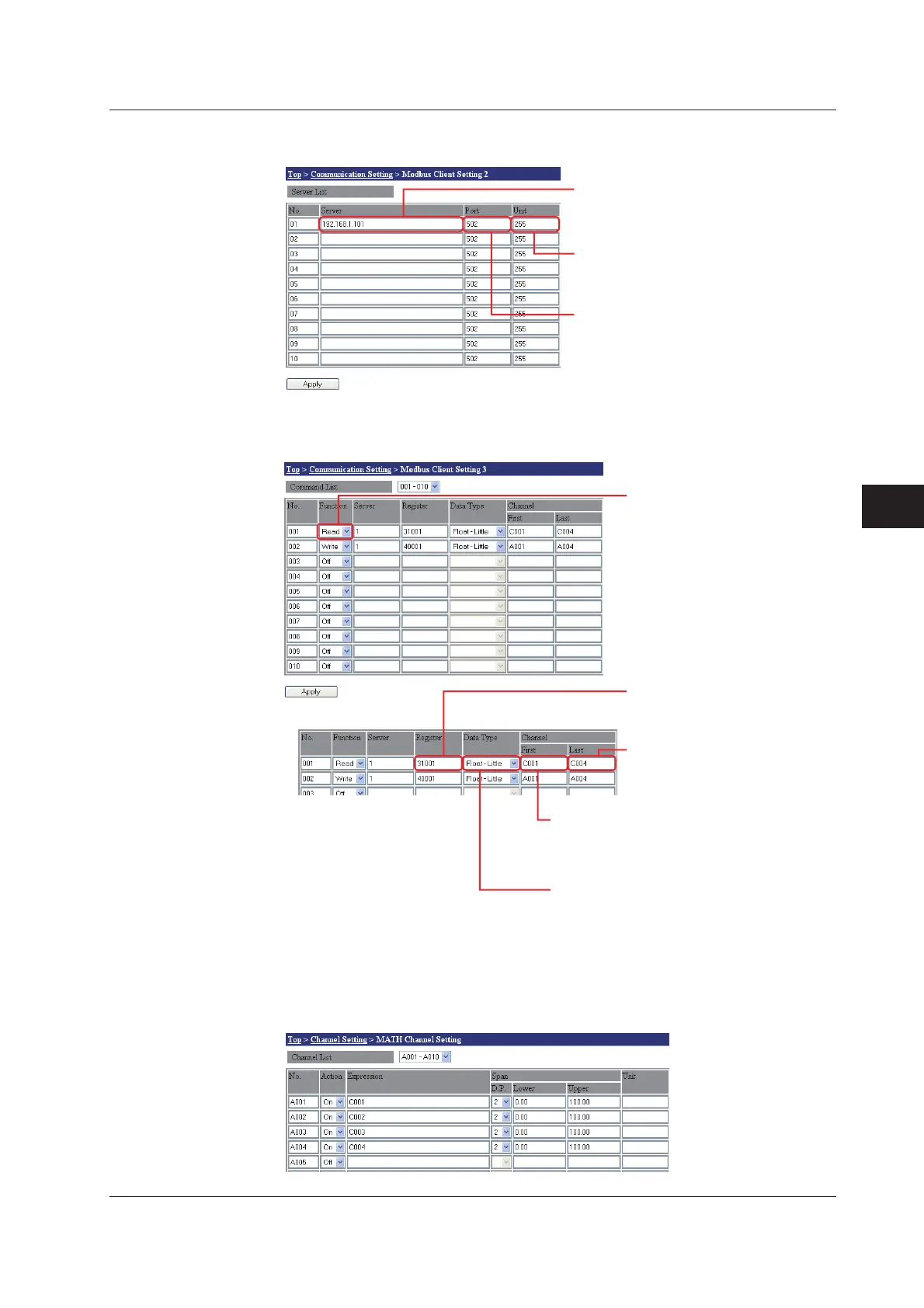
Client Setting 2
Enter settings for the destination server.
Enter the IP address of the server
Enter the IP address or host name of the destination
server. In the example, an IP address of
“192.168.1.101” is entered.
Enter the server unit number
Only Modbus/TCP connections are used in the
example, therefore the default unit number of “255”
is used.
Enter the server port number
Enter the port number of the destination server.
In the example, “502” is entered.
Client Setting 3
Enter settings for registers to be used for receiving data. For data types, see “Register
Data Types.”
Select the register function (read
or write)
If the client will be reading from the
server, select “Read.”
Enter the number of the destination
server
Enter the number set in Client Setting 2.
In the example, “1” is entered.
Enter the communication input
channels on which to read by the
client
In the example, the client will read on
communication input channels “C001” to “C004.”
• for Read
Select the data type for the registers on the
destination server that will be read.
In the example, “Float-Little” is entered indicating that the
register data type is 32-bit floating point and the order is
lower byte, upper byte.
Enter the number of the first input register on
the destination server that will be read.
In the example, “31001” is entered since the measured data
read out from measurement channels 001 to 004 is of the
32-bit floating point type.
MATH Channel Settings
In order to display data loaded to the communication input channels from the MW100
server, enter the communication input channel numbers in the MATH channel expression
entry area.
Appendix 2 Setting Data Communication That Uses Modbus Protocol

 Loading...