2-15
IM MW100-01E
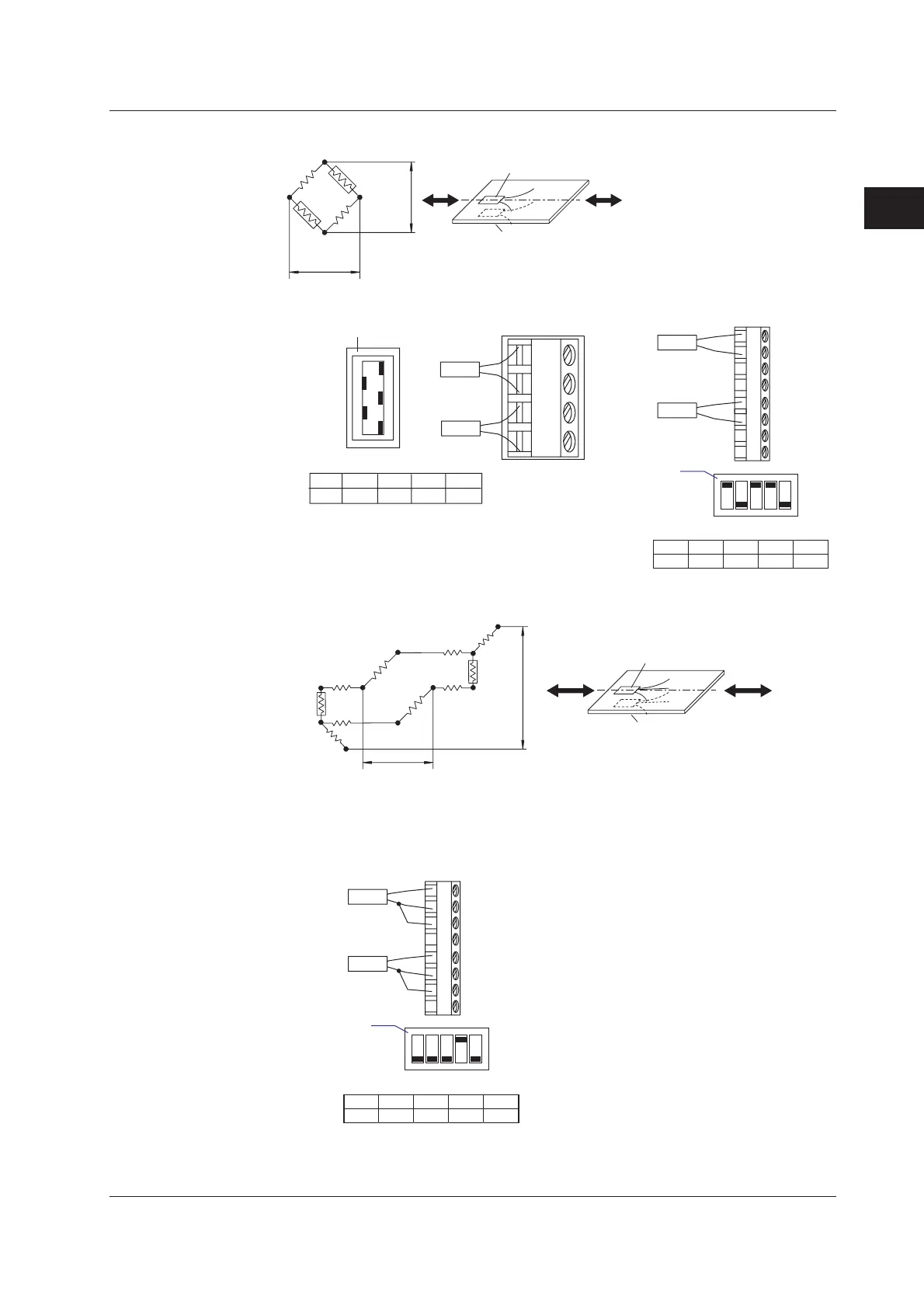
Installation and Wiring
2
2.4 Connecting Signal Wires
• Opposing 2 Gauge Method
ON
OFF
No.1
No.2
No.3
No.4
No.5
A(+V)
B( L)
C(-V)
D( H)
No.1
ON
No.2
OFF
No.3
ON
No.4
OFF
No.5
ON
Rg1
Rg2
R
R
Rg2
Rg1
E
e
Rg1
Rg2
Jumper setting switch
-B12, -B35
R: fixed resistance
r: resistance value of lead wire
Rg: resistance value of strain
gauge
e: output voltage from bridge
E: voltage applied to bridge
-NDI
Bridge head
switch
Rg1
Rg2
ON
1 2 3 4 5
1
2
3
4
5
6
7
8
OFF
SW
Bridge head
(701955 or 701956)
SW1
ON
SW2
OFF
SW3
ON
SW4
ON
SW5
OFF
• Opposing 2 Gauge 3 Wire Method
R
R
Rg2
Rg1
E
e
Rg1
Rg2
Cannot be connected. Use -NDI.
r
r
r
r
r
r
-B12, -B35
R: fixed resistance
r: resistance value of lead wire
Rg: resistance value of strain gauge
e: output voltage from bridge
E: voltage applied to bridge
-NDI
Bridge head
switch
Rg1
ON
1 2 3 4 5
1
2
3
4
5
6
7
8
OFF
SW
Bridge head
(701955 or 701956)
SW1
OFF
SW2
OFF
SW3
OFF
SW4
ON
SW5
OFF
Rg2

 Loading...