3-60
Confidential
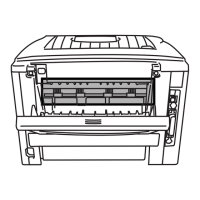
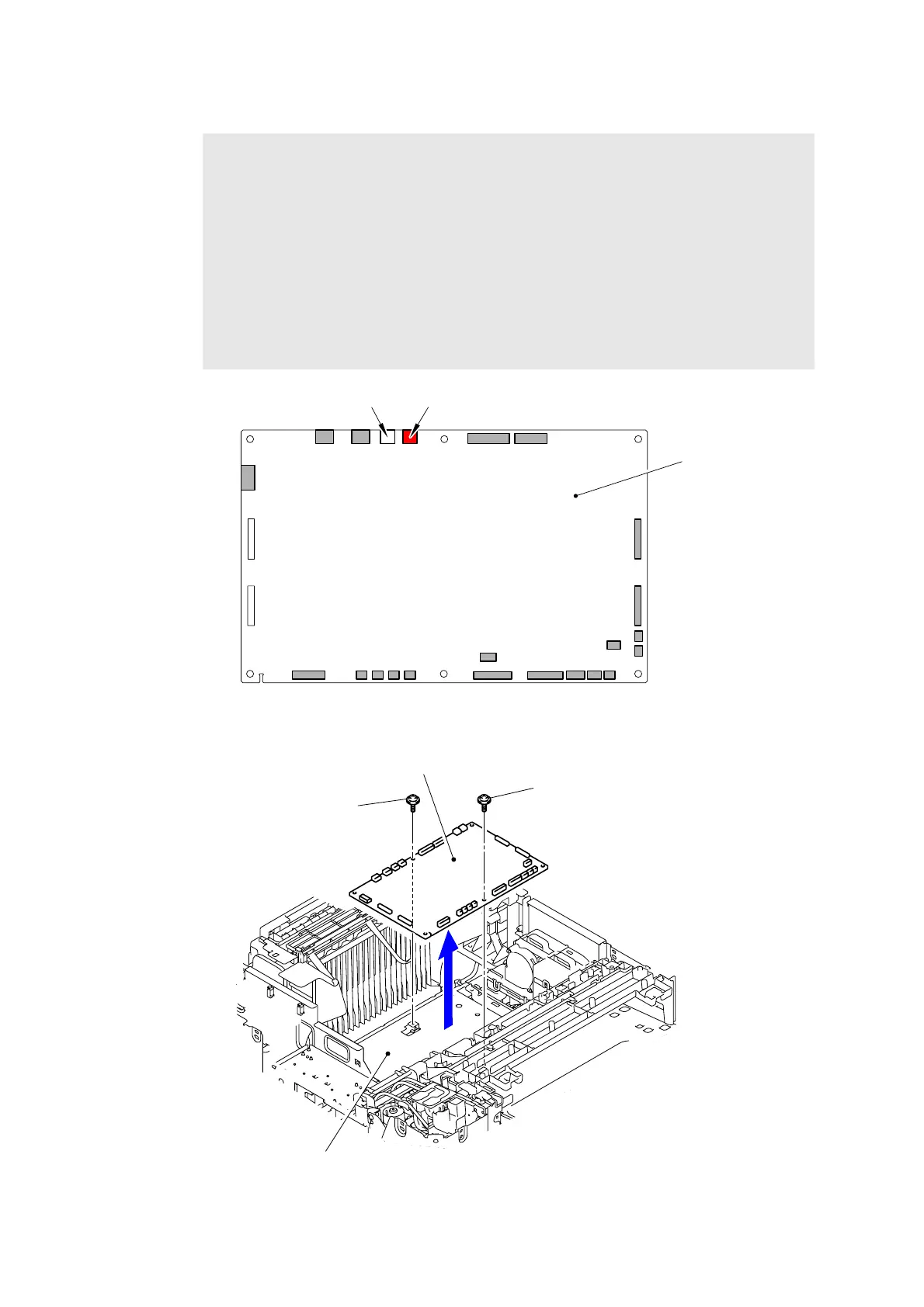
(3) Disconnect the all Connectors from the Engine PCB ASSY.
Fig. 3-54
(4) Remove the two Taptite cup S M3x6 SR screws to remove the Engine PCB ASSY.
Fig. 3-55
Note:
- After disconnecting flat cable(s), check that each cable is not damaged at its end or
short-circuited.
- When connecting flat cable(s), do not insert them at an angle. After insertion, check
that the cable are not at an angle.
- Among the two harnesses in the Fan unit, the fan at the side of red connector cannot
be checked upon initial operation check, and therefore even if the harness is not
inserted, no error occurs. Be sure to visually check that the harness is fully inserted
at the time of assembly.
- For the products which have only one fan in the Fan unit, be sure to insert the
harness of the Fan unit to the white connector. If it is connected to the red connector,
an error of the unconnected Fan unit harness occurs.
Engine PCB ASSY
Connector (red)Connector (white)
Taptite cup S M3x6 SR
Taptite cup S M3x6 SR
Engine PCB ASSY
<Front>
Engine PCB base plate

 Loading...