5
5
5-14
5-14
Troubleshooting > Connector Layout Drawing
Troubleshooting > Connector Layout Drawing
■
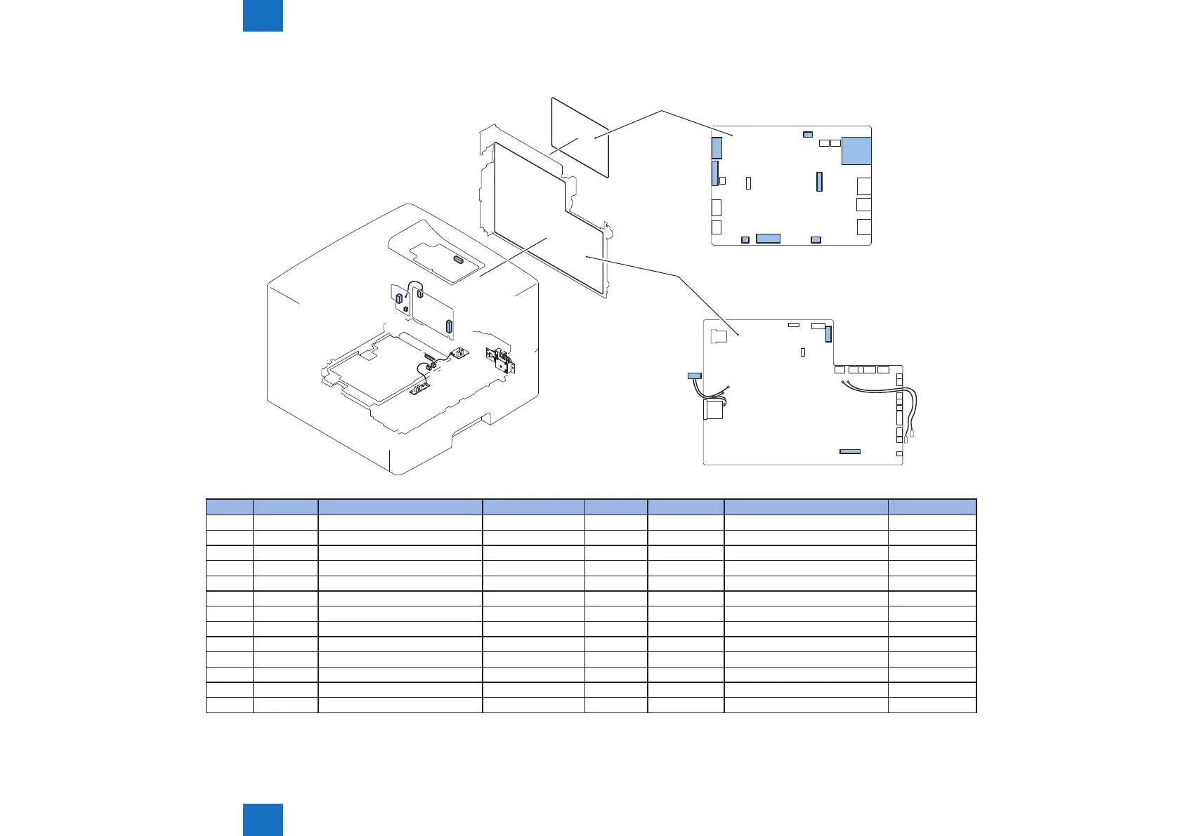
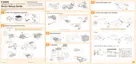
Connectors Layout Drawing (LBP3580/6780x) (1/3)
J1301
J1
J1101
J681
J691
J501
J211
J507
J513
J120
J18
J505 J3 J502
J302
J1400
J4
Main Controller PCB
J1701
J1101
J1610
Engine Controller
PCB
J No. Symbol Name Relay connector J No. Symbol Name Remarks
J1701 - Engine Controller PCB J18 - Main Controller PCB
J1610 - Engine Controller PCB J501 - High Voltage Power Supply Unit
J1101 - Engine Controller PCB J1101 - AC Relay PCB
J3 - Main Controller PCB J691 - All-night Power Supply PCB
J4 - Main Controller PCB - - USB Slot
J120 - Main Controller PCB J1 - Control Panel PCB
J302 - Main Controller PCB - - SD Card Slot
J502 - Main Controller PCB J211 - AC Relay PCB
J505 - Main Controller PCB J1301 SW1301 Power Switch
J1400 - Main Controller PCB J1 - Sub Log PCB
J681 - AC Relay PCB J681 - All-night Power Supply PCB
J513 - High Voltage Power Supply Unit J513 PS225 Paper Width Sensor
J507 - High Voltage Power Supply Unit J507 PS215 Top Sensor
F-5-27
T-5-25