5
5
5-15
5-15
Troubleshooting > Connector Layout Drawing
Troubleshooting > Connector Layout Drawing
■
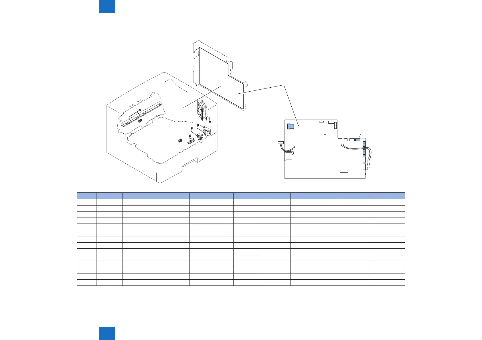
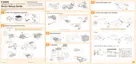
Connectors Layout Drawing (LBP3580/6780x) (2/3)
J6
J2
J15
J15B
J15C
J1602
J1604
J19
J1601
J1002
J1002B
J1002C
J1608
J1602
J1606
J1604
J1601
J1603
J1606
Engine Controller PCB
J No. Symbol Name Relay connector J No. Symbol Name Remarks
J1608 - Engine Controller PCB J18 J19 TH1 Fixing Sub Thermistor
J1608 - Engine Controller PCB J18 J19 TH2 Fixing Main Thermistor
J1608 - Engine Controller PCB J24 J2 PS2 Fixing Delivery Sensor
J1002 - Engine Controller PCB J15 H1 Fixing Heater 120V
J1002B - Engine Controller PCB J15B H2 Fixing Heater 200V
J1002C - Engine Controller PCB J15C H3 Fixing Heater 100V
J1002 - Engine Controller PCB - TP1 Fixing Thermo Switch 120V
J1002B - Engine Controller PCB - TP1B Fixing Thermo Switch 200V
J1002C - Engine Controller PCB - TP1C Fixing Thermo Switch 100V
J1602 - Engine Controller PCB J1602 SL1 Multi-purpose Tray Pickup Solenoid
J1601 - Engine Controller PCB J1601 SL2 Cassette Pickup Solenoid
J1603 - Engine Controller PCB J6 PS3 Cassette Paper Sensor
J1604 - Engine Controller PCB J1604 PS205 Multi-purpose Tray Paper Sensor
J1606 - Engine Controller PCB J1606 FM1 Main Fan
F-5-28
T-5-26