EasyManuals Logo

Cisco ASR 1002-X Hardware Installation Guide

Cisco ASR 1002-X
702 pages
To Next Page IconTo Next Page
To Previous Page IconTo Previous Page
Page #112 background imageLoading...
Page #112 background image
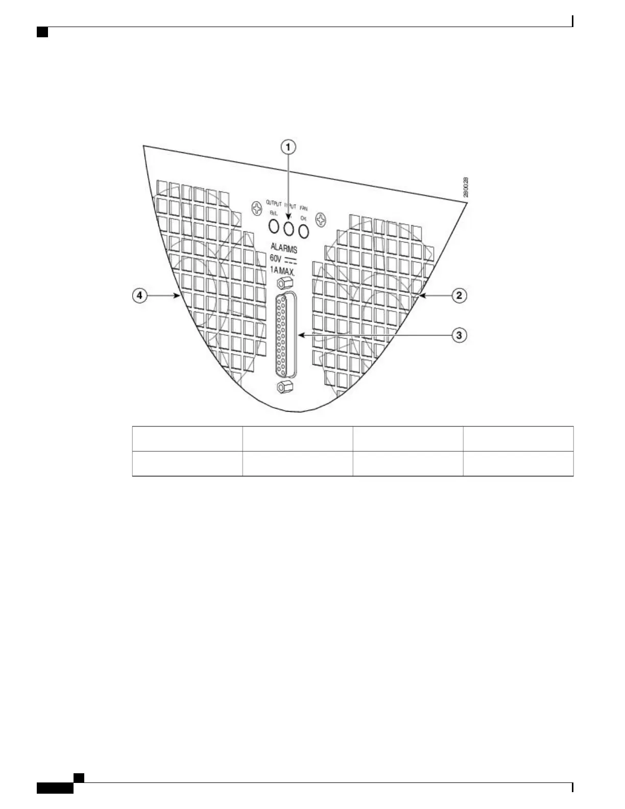
The following figure shows the AC power supplies LEDs and DB-25 Alarm connector.
Figure 20: Cisco ASR 1013 Router AC Power Supply LEDs and DB-25 Alarm Connector
DB-25 alarm connector3AC power supply LEDs1
AC power supply fan4AC power supply fan2
The following table describes the AC power supply LEDs on the Cisco ASR 1013 Router.
Cisco ASR 1000 Series Router Hardware Installation Guide
78
Cisco ASR 1000 Series Routers Component Overview
AC Power Supply LEDs and Connector for Cisco ASR 1013

Table of Contents

Other manuals for Cisco ASR 1002-X

Questions and Answers:

Question and Answer IconNeed help?

Do you have a question about the Cisco ASR 1002-X and is the answer not in the manual?

Cisco ASR 1002-X Specifications

General IconGeneral
Form FactorRack-mountable
Rack Units2RU
Integrated ServicesYes
Maximum Memory16 GB
Built-in Gigabit Ethernet Ports6
Input Voltage100-240 VAC
Operating Temperature32 to 104°F (0 to 40°C)
RedundancyPower supply redundancy
Network Interface ModulesUp to 4 SPA/SIP slots
Embedded Services Processor (ESP)ESP-20
Maximum Packet per Second (PPS)15 Mpps
Height3.5 inches
Fixed Ports6 GE ports
Memory4 GB (default), 16 GB (maximum)
Power SupplyDual power supplies (AC or DC)
Dimensions (H x W x D)3.5 x 17.5 x 19.0 in (8.9 x 44.5 x 48.3 cm)

Related product manuals