Make certain that the cable-management bracket “U” feature device has the open end pointing upwards when
you attach it to the chassis
Note
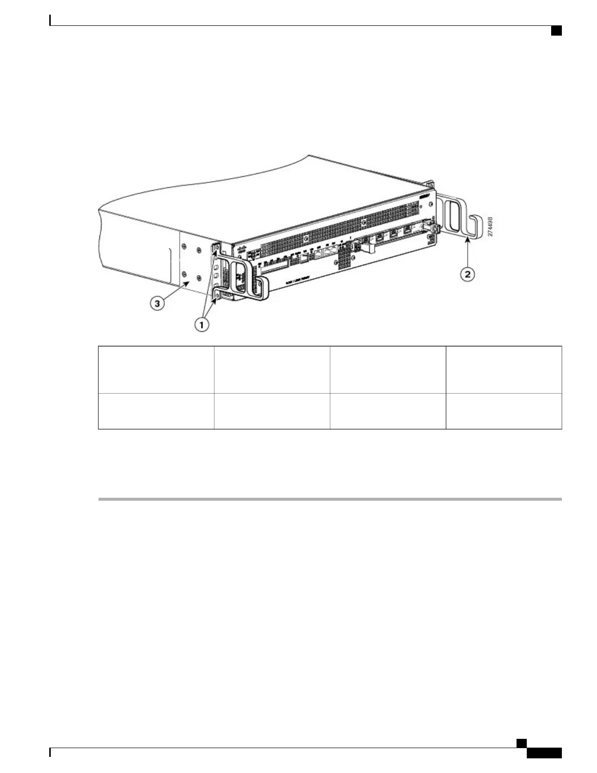
Figure 125: Attaching the Cable-Management Brackets to the Cisco ASR 1002-F Router
Chassis front rack-mount
bracket
3Cable-management bracket
top screw hole and bottom
screw hole
1
——
Cable-management bracket
“U” feature
2
Step 8
Screw the cable-management brackets to each side of the rack-mount brackets already attached to the chassis. Use two
screws for each cable-management bracket.
Step 9
Check that all the screws are securely tightened.
What to Do Next
Go to the Attaching a Chassis Ground Connection, on page 302 to continue the installation.
Rack-Mounting the Cisco ASR 1002-F Router
The Cisco ASR 1002-F Router can be installed in an existing rack with equipment or in an empty rack with
no equipment. The chassis can be mounted in two equipment rack types:
•
Two-post rack, 19-inch or 23-inch equipment rack. Inner clearance (the width between the inner sides
of the two posts or rails) must be at least 19 inches (48.26 cm). The height of the chassis is 3.47 inches
(8.8 cm). Airflow through the chassis is from front to back
.
Cisco ASR 1000 Series Router Hardware Installation Guide
291
Cisco ASR 1002-F Router Overview and Installation
Rack-Mounting the Cisco ASR 1002-F Router
 Loading...


