EasyManuals Logo

Cisco ASR 1002-X Hardware Installation Guide

Cisco ASR 1002-X
702 pages
To Next Page IconTo Next Page
To Previous Page IconTo Previous Page
Page #438 background imageLoading...
Page #438 background image
To reduce the chance of interference, avoid crossing high-power lines with any interface cables.
Verify all cabling limitations (particularly distance) before powering on the system.
Attaching Cable Retention Bracket on AC Power Supply
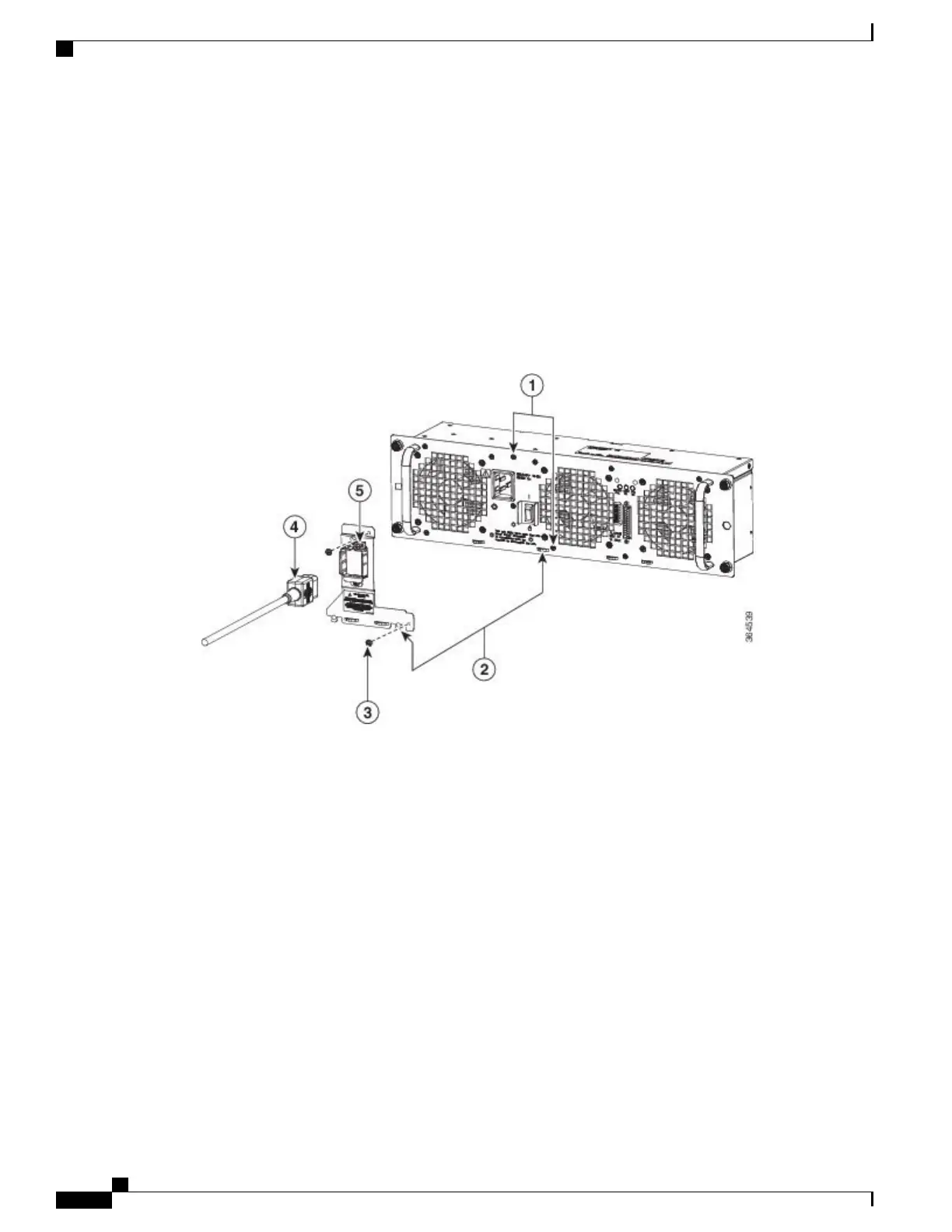
This section explains how to attach the cable retention bracket on AC power supply of the chassis.
The following image shows the cable retention bracket attaching to the AC power supply.
Figure 195: Cable Retention Bracket Attaching to the AC Power Supply
SUMMARY STEPS
1.
Remove the two M3X5mm screws and discard.
2.
Install AC cord retainer by inserting tabs into lance features on panel.
3.
Secure AC cord retainer with two M3X8mm screws included in kit.
4.
Connect AC power cord.
5.
Secure AC cord by tightening retainer screw.
Cisco ASR 1000 Series Router Hardware Installation Guide
404
Cisco ASR 1013 Router Overview and Installation
Attaching Cable Retention Bracket on AC Power Supply

Table of Contents

Other manuals for Cisco ASR 1002-X

Questions and Answers:

Question and Answer IconNeed help?

Do you have a question about the Cisco ASR 1002-X and is the answer not in the manual?

Cisco ASR 1002-X Specifications

General IconGeneral
Form FactorRack-mountable
Rack Units2RU
Integrated ServicesYes
Maximum Memory16 GB
Built-in Gigabit Ethernet Ports6
Input Voltage100-240 VAC
Operating Temperature32 to 104°F (0 to 40°C)
RedundancyPower supply redundancy
Network Interface ModulesUp to 4 SPA/SIP slots
Embedded Services Processor (ESP)ESP-20
Maximum Packet per Second (PPS)15 Mpps
Height3.5 inches
Fixed Ports6 GE ports
Memory4 GB (default), 16 GB (maximum)
Power SupplyDual power supplies (AC or DC)
Dimensions (H x W x D)3.5 x 17.5 x 19.0 in (8.9 x 44.5 x 48.3 cm)

Related product manuals