The output voltage alarm is raised when the output voltage is below the low end of the minimum limit or
above the high end of the maximum limit. When the output voltage is above the high end of the minimum or
below the low end of the maximum limit, the red state is not activated.
The following table shows the –48 VDC power supply output voltage alarm ranges.
Table 72:
–
48 VDC Power Supply Output Voltage Alarm Threshold Ranges
MaximumMinimumOutput
12.8-13.8 V10.0-11.2 V12 V
None2.6-3.0 V3.3 V
+24 VDC Power Supply for the Cisco ASR 1002-X Router
This section provides information about the +24 VDC power supply at the rear of the Cisco ASR 1002-X
Router. The recommended branch circuit breaker for the Cisco ASR 1002-X Router +24 VDC power supply
is a 40 A UL-listed circuit breaker.
The Cisco ASR 1002-X Router has two same-type power supplies in power supply slot 0 and power supply
slot 1. The power supply slot identifiers are zero (0) on the left side of the chassis, rear side, and one (1) on
the right side of the chassis, rear side. The power supply switch is a Standby switch and is not considered a
disconnect.
The +24 VDC power supply uses a spring-loaded terminal block. The input terminal block requires a maximum
of 8 AWG multistrand wiring to support the input current. The terminal block is compliant with safety agencies’
guidelines and the electrical requirements of the supply. Use the tie wraps to dress the input cable wires; there
are two tie wrap tabs on the +24 VDC power supply. The +24 VDC power supply unit is secured into the
system chassis with two captive screws mounted on the faceplate.
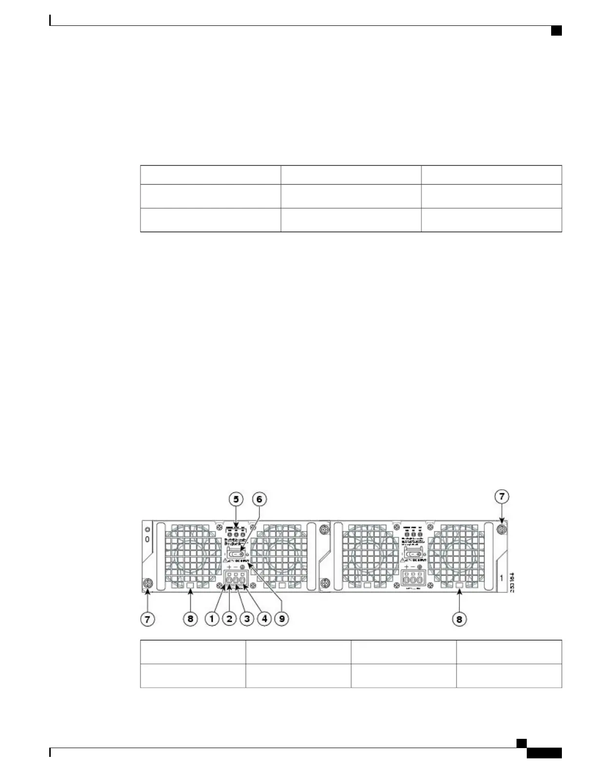
The following image shows the +24 VDC power supply for the Cisco ASR 1002-X Router.
Figure 150: Cisco ASR 1002-X Router +24 VDC Power Supply
Standby/On switch6+24 VDC terminal block1
Captive fastener7Positive (+) lead2
Cisco ASR 1000 Series Router Hardware Installation Guide
327
Cisco ASR 1002-X Router Overview and Installation
Power Supplies in the Cisco ASR 1002-X Router
 Loading...


