The chassis rack-mounting flanges are secured directly to the chassis before you lift it into the rack.Note
Verifying Rack Dimensions
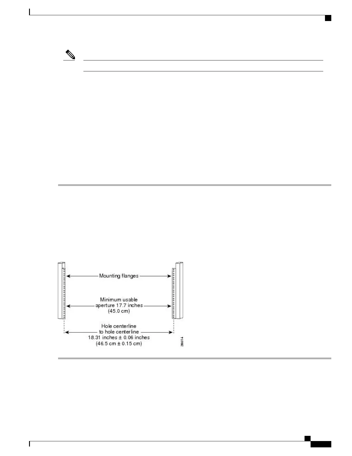
Before you install the chassis, measure the space between the vertical mounting flanges (rails) on your
equipment rack to verify that the rack conforms to the measurements shown in the following image.
SUMMARY STEPS
1.
Mark and measure the distance between two holes on the left and right mounting rails.
2.
Measure the space between the inner edges of the left front and right front mounting flanges on the
equipment rack.
DETAILED STEPS
Step 1
Mark and measure the distance between two holes on the left and right mounting rails.
The distance should measure 18.31 inches ± 0.06 inches (46.5 cm ± 0.15 cm).
Measure for pairs of holes near the bottom, middle and top of the equipment rack to ensure that the rack posts
are parallel.
Note
Step 2
Measure the space between the inner edges of the left front and right front mounting flanges on the equipment rack.
The space must be at least 17.7 inches (45 cm) to accommodate the chassis which is 17.25 inches (43.8 cm) wide and
fits between the mounting posts on the rack.
Figure 64: Verifying Equipment Rack Dimensions
Cisco ASR 1000 Series Router Hardware Installation Guide
191
Cisco ASR 1004 Router Overview and Installation
Verifying Rack Dimensions
 Loading...


