DescriptionDirectionSignalPin
Receive DataInRXD6
Data Set Ready/Data
Carrier Detect
InDSR/DCD7
Clear to SendInCTS8
Cisco ASR 1006 Router DB-25 Pinout Assignments for Alarm Relays
The alarm ports for the Cisco ASR 1006 Router (Cisco ASR 1004 Router and Cisco ASR 1013 Router) power
supplies reside on the DB-25 connector on the face of the power supply. The alarm ports are relay contact
closures that the IOS environmental software controls. The environmental monitoring functions of the system
can include voltage and temperature monitoring for the router installed components and failure sensing for
power supply fan tray.
Any alarms that light the front panel LEDs on the Cisco ASR1000-RP1 causes a contact closure between the
corresponding pins within the DB-25 alarm port of both power supplies. In the DB-25 connector, each alarm
consists of a three-pin set containing a common pin, a normally open pin, and a normally closed pin. The
connections that describe alarm activity are Alarm off (Common is connected to normally closed and normally
open is disconnected) and Alarm on (Common is connected to normally open and normally closed is
disconnected).
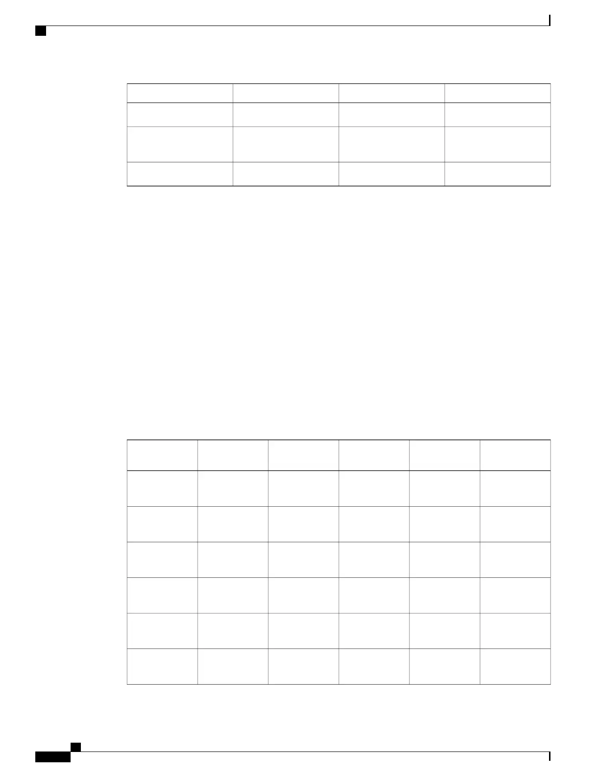
The following table lists the common, normally open, and normally closed relay contacts accessible to an
external alarm monitoring facility by means of the DB-25 connector.
Table 102: Cisco ASR 1006 Router DB-25 Alarm Connector Pinout Assignments
SPARENormally Closed
(NC)
Normally Open
(NO)
Common
(CM)
DescriptionSignal
—
1412Critical Audible
Alarm
CRTAA
—
15316Major Audible
Alarm
MAJAA
—
1745Minor Audible
Alarm
MINAA
—
18619Critical Visual
Alarm
CRTVA
—
2078Major Visual
Alarm
MAJVA
—
21922Minor Visual
Alarm
MINVA
Cisco ASR 1000 Series Router Hardware Installation Guide
620
Cisco ASR 1000 Series Router Specifications
Cisco ASR 1006 Router DB-25 Pinout Assignments for Alarm Relays

 Loading...


