Cisco ASR 1004 Router –48 VDC Power Supply LEDs and Connector
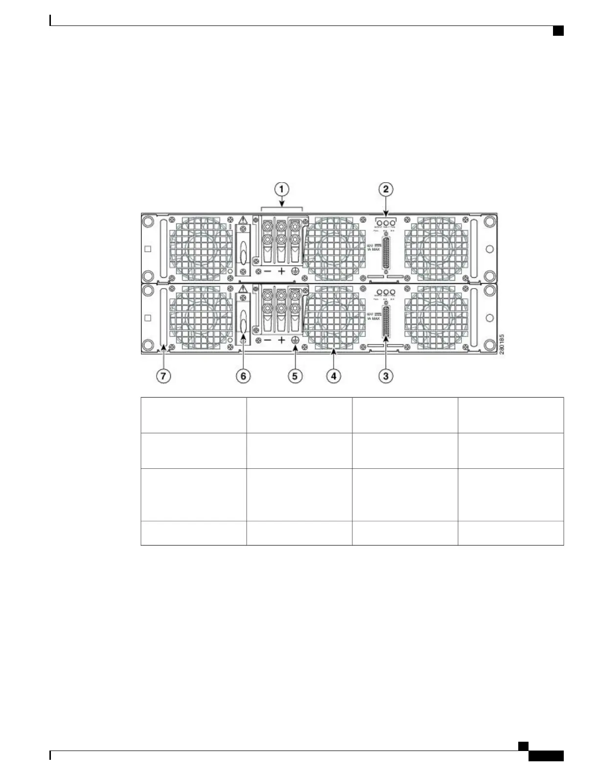
The following figure shows the –48 VDC power supplies at the rear of the Cisco ASR 1004 Router. The Cisco
ASR 1004 Router supports up to two power supplies.
Figure 15: Cisco ASR 1004 Router
–
48 VDC Power Supply
Grounding symbol5Terminal and plastic
cover
1
Power supply On (|) /Off
(O) switch
6Power supply LEDs2
Power supply handle7DB-25 alarm connector
Power supply ground lugs
(+ and –)
3
——
Power supply fan4
The following table describes the power supply LEDs and connectors on the rear of the chassis.
Cisco ASR 1000 Series Router Hardware Installation Guide
63
Cisco ASR 1000 Series Routers Component Overview
Cisco ASR 1004 Router –48 VDC Power Supply LEDs and Connector

 Loading...


