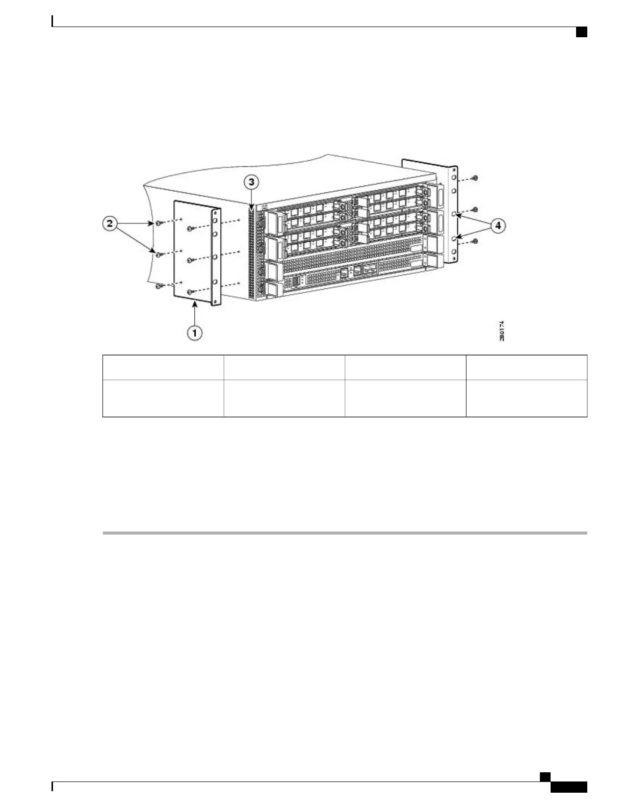
The following shows where to attach the front rack-mount brackets to the Cisco ASR 1004 Router.
Figure 65: Attaching the Front Rack-Mount Brackets to the Cisco ASR 1004 Router
Chassis side vent holes3Front rack-mount bracket1
Front rack-mount bracket
and ear holes
4Front rack-mount bracket
screws
2
Step 2
Position the front rack-mount bracket top hole with the chassis first top hole behind the side vent holes.
Step 3
Insert and tighten the black screws on one side.
Step 4
Repeat Step 1 through Step 3 on the other side of the chassis. Use black screws to secure the rack-mount brackets to the
chassis.
Step 5
Install the chassis in a rack. To install the Cisco ASR 1004 Router in a rack, go to the Installing the Cisco ASR 1004
Router in a Rack, on page 195.
What to Do Next
This completes the steps for attaching the front rack-mount brackets to the Cisco ASR 1004 Router.
Chassis Rear Rack-Mount Brackets
If you are rack-mounting the chassis using the rear rack-mount brackets, then this type of installation provides
for the chassis being recessed in the rack.
To install the front rack-mount brackets on the Cisco ASR 1004 Router, perform the following steps:
Cisco ASR 1000 Series Router Hardware Installation Guide
193
Cisco ASR 1004 Router Overview and Installation
Chassis Rear Rack-Mount Brackets
 Loading...


