When handling the chassis, always follow proper lifting practices. See the “Chassis-Lifting Guidelines”
section on page 5-23 .
Note
The Cisco ASR 1002-X Router can be installed with both front or rear rack mount brackets.
Verifying Rack Dimensions
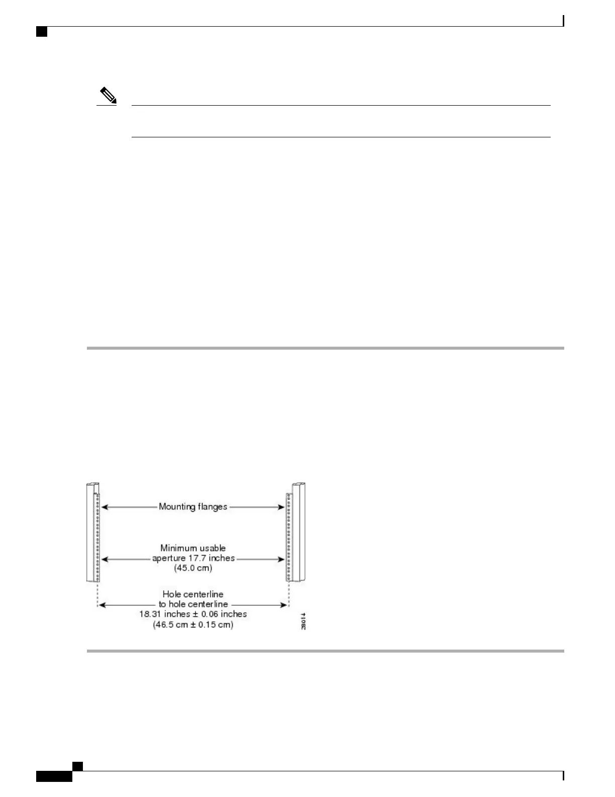
Before you install the chassis, measure the space between the vertical mounting flanges (rails) on your
equipment rack to verify that the rack conforms to the measurements shown in the following image.
SUMMARY STEPS
1.
Mark and measure the distance between the holes on the left and right mounting rails.
2.
Measure the space between the inner edges of the left front and right front mounting flanges on the
equipment rack.
DETAILED STEPS
Step 1
Mark and measure the distance between the holes on the left and right mounting rails.
The distance should measure 18.31 inches ± 0.06 inches (46.5 cm ± 0.15 cm).
Measure for pairs of holes near the bottom, middle, and top of the equipment rack to ensure that the rack posts
are parallel.
Note
Step 2
Measure the space between the inner edges of the left front and right front mounting flanges on the equipment rack.
The space must be at least 17.7 inches (45 cm) to accommodate the chassis that is 17.25 inches (43.8 cm) wide and fits
between the mounting posts on the rack.
Figure 153: Verifying the Equipment Rack Dimensions
Cisco ASR 1000 Series Router Hardware Installation Guide
336
Cisco ASR 1002-X Router Overview and Installation
Verifying Rack Dimensions
 Loading...


