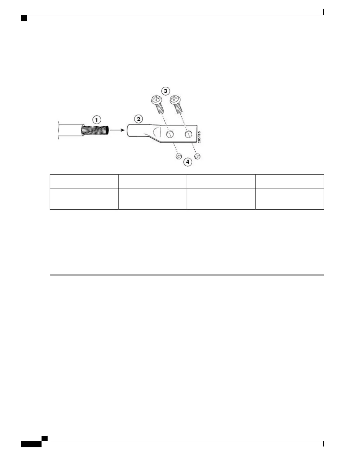
The following image shows how to attach a grounding lug to the chassis ground connector.
Figure 213: Attaching a Grounding Lug to the Chassis Ground Connector
Ground screws3Chassis ground lead wire1
Chassis ground connector
holes
4Grounding stud2
Step 5
Locate the chassis ground connector on the side of your chassis.
Step 6
Insert the two screws through the holes in the grounding lug.
Step 7
Use the Number 2 Phillips screwdriver to carefully tighten the screws until the grounding lug is held firmly to the chassis.
Do not overtighten the screws.
Step 8
Connect the opposite end of the grounding wire to the appropriate grounding point at your site to ensure an adequate
chassis ground.
What to Do Next
This completes the procedure for attaching a chassis ground connection.
Connecting the Shared Port Adapter Cables
The instructions for connecting the cables for the shared port adapter installed in the Cisco ASR 1001 Router
are contained in the respective configuration documents for each port adapter. For example, if you are
connecting the optical fiber cables for the PA-POS-OC3 port adapter, see PA-POS-OC3 Port Adapter
Installation and Configuration at the following location:
http://www.cisco.com/en/US/partner/docs/interfaces_modules/port_adapters/install_upgrade/pos/
pa-pos-oc3_install_config/paposoc3.html
Cisco ASR 1000 Series Router Hardware Installation Guide
440
Cisco ASR 1001 Router Overview and Installation
Connecting the Shared Port Adapter Cables
 Loading...


