24 VDC Power System Input for Cisco ASR 1002 Router
The +24 VDC power supply operates within specification between +21 and +36 VDC continuously once the
power supply DC input is turned on. The power supply shall measure the input voltage at the terminals of the
power supply and turn off the supply when the input voltage reaches 19.0 volts +/- 0.5 volts. Once this low
voltage threshold is reached, the power supply does not resume operation until the input voltage has reached
20.0 volts +/- 0.5 volts. Once the turn-on threshold of 20 volts is reached, then the +24 VDC power supply
meets all specification requirements down to low voltage threshold of 19 volts (+/- tolerance).
+24 VDC Power System Output for Cisco ASR 1002 Router
The +24 VDC power supply output tolerance is defined in Cisco ASR 1002 Router +24 VDC Power System
Output Voltage and Current table under all combinations of +24 VDC input line variation. Total system power
consumption should not exceed 470 watts or output rating of each power supply.
Two power supplies are used for redundant operation. System total power consumption shall never exceed
rating of one power supply to maintain redundancy.
Note
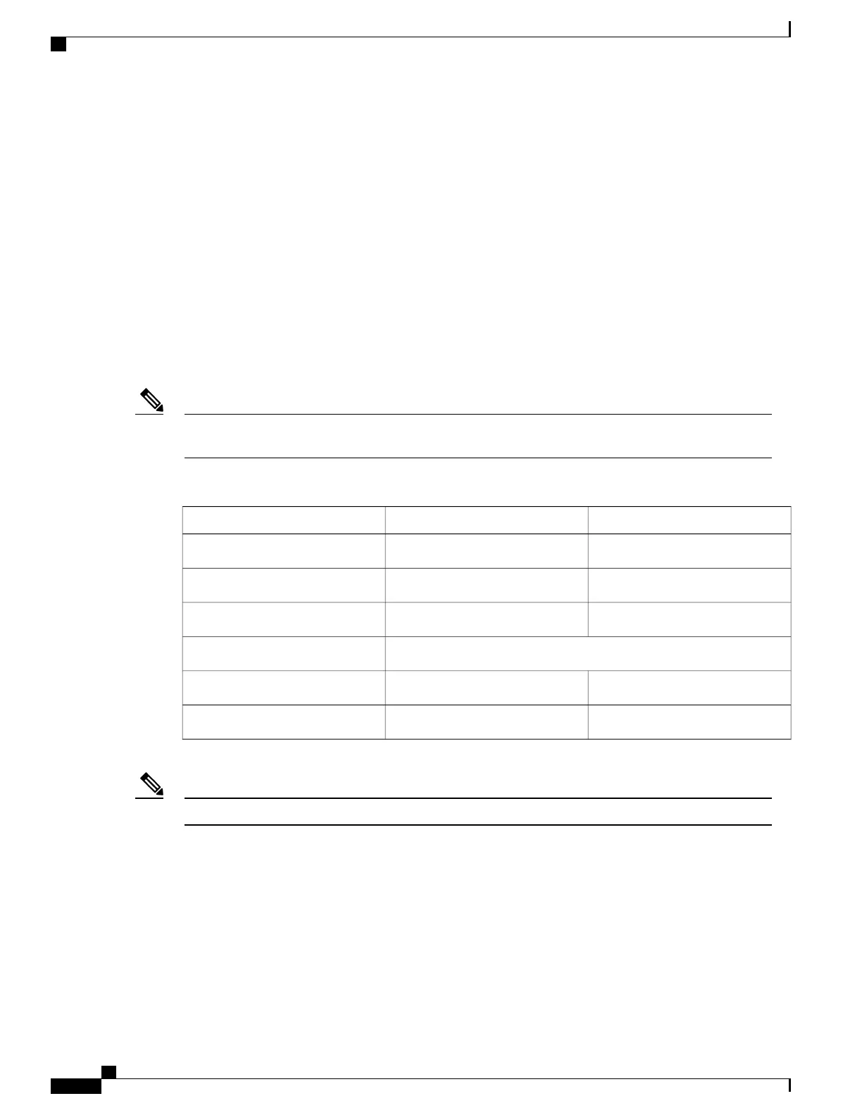
Table 57: Cisco ASR 1002 Router +24 VDC Power System Output Voltage and Current
+3.3 V+12 VDCOutput Voltage
3.2011.80Minimum
3.3012.00Nominal
3.4012.20Maximum
Output Current
0.10 A2.0 AMinimum
3.125 A39 AMaximum
Any combination of output voltage/currents cannot exceed total power rating of 470 Watts.Note
+24 VDC Power Supply Important Notices
The following items list important notes regarding the +24 VDC power supply in the Cisco ASR 1002 Router:
• Output Voltage Alarm Threshold—The Output Voltage Alarm is declared when the output voltage is
below the low end of the minimum or above the high end of the maximum limits (as shown in VDC
Output Voltage Alarm Threshold Ranges table). When the output voltage is above the high end of the
minimum or below the low end of the maximum limits, then the Red state is not activated.
Cisco ASR 1000 Series Router Hardware Installation Guide
232
Cisco ASR 1002 Router Overview and Installation
Power Supplies in the Cisco ASR 1002 Router

 Loading...


